A kind of electrolytic grinding device for realizing rotating liquid and its working method

A technology of electrolytic grinding and rotary pass, which is applied in the field of electric machining, can solve the problems of low precision in reassembly, time-consuming clamping, and influence on machining accuracy, etc., and achieve the goal of improving the efficiency of reassembly, good liquid supply effect, and expanding engineering applications Effect

Inactive Publication Date: 2015-11-18
NANJING UNIV OF AERONAUTICS & ASTRONAUTICS
View PDF8 Cites 0 Cited by
  • Summary
  • Abstract
  • Description
  • Claims
  • Application Information

AI Technical Summary

Problems solved by technology

In particular, for some workpieces with special geometric shapes, such as electrolytic grinding of inner holes and inner cavities, it is difficult to meet the normal supply of electrolyte with a certain flow rate in all processing areas by using the spray liquid supply method.
[0006] In addition, conductive grinding wheels often need to be trimmed, which is often difficult to complete online trimming. The repeated disassembly and clamping are time-consuming and labor-intensive, and the replacement accuracy is generally low. Adjustment and alignment are required to meet the replacement accuracy requirements , which will have a certain impact on the machining accuracy

Method used


Image

  • A kind of electrolytic grinding device for realizing rotating liquid and its working method
  • A kind of electrolytic grinding device for realizing rotating liquid and its working method

Examples


Embodiment Construction

[0021] The present invention will be further described below in conjunction with accompanying drawing.

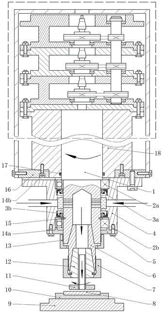
[0022] figure 1 It is a structural schematic diagram of an embodiment of the present invention. The upper dotted line frame is an electrolytic grinding device that realizes high-current and high-speed conduction. It has applied for a patent, and the application number is 201310125655.7. This part uses a coupling to connect multiple identical conductive rings in series, and the conductive ring rotor is connected to the high-speed coupling. , the stator is connected to the low-speed coupling, and the pulley transmission is used to distribute the speed of each coupling, so that the relative speeds of the rotor and the stator of each conductive ring are equal, and the low-speed conductive ring is used for several times the rated value of the rotor and stator. Continuous power supply of the conductive grinding wheel at high speed. The present invention can realize top-to-botto...


PUM


Abstract

The invention provides an electrolytic grinding device capable of realizing rotary solution feeding and a working method thereof. The electrolytic grinding device comprises a motorized spindle stator and a motorized spindle rotor. A blind hole is formed inside the end, extending outside, of the motorized spindle rotor, the lower end of the motorized spindle rotor is connected with a conductive grinding wheel through a clamping device, a plurality of through holes are formed in the radial direction of the motorized spindle rotor, and a first sealing ring and a second sealing ring are arranged above and below the through holes respectively for sealing the same. An outer cover is arranged on the outer side of the motorized spindle rotor, and middle holes are formed in positions, corresponding to the through holes, of the outer cover. A first bearing and a second bearing are arranged between the motorized spindle rotor and the outer cover. An electrolyte solution passes through the middle holes of the outer cover, enters the inside blind hole from the through holes of the end, extending outside, of the motorized spindle rotor, and then passes a center hole of the clamping device to outflow around from clearances of the conductive grinding wheel and a workpiece. The electrolytic grinding device is low in requirement on pressure and flow of the electrolyte solution, good in solution feeding effect, and particularly suitable for electrolytic grinding of workpieces such as inner holes and inner cavities in special geometrical shapes.

Description

technical field [0001] The invention relates to the technical field of electric machining, in particular to an electrolytic grinding device and a working method thereof for realizing rotary fluid passage. Background technique [0002] Electrolytic grinding is a composite processing method that combines electrolytic and mechanical grinding. It has higher precision and surface quality than electrolytic machining, higher efficiency and stability than mechanical grinding, and the wear of the grinding wheel is small. , suitable for grinding all kinds of conductive metal materials with high strength, high hardness, heat sensitivity, brittleness, etc. which are difficult to grind. [0003] In the process of electrolytic grinding, the following two conditions must be met at the same time. One is that the conductive grinding wheel must pass a large current while rotating, and the other is that the electrolyte must be continuously supplied with a certain flow rate between the conducti...

Claims


Application Information

Patent Timeline
Patent Type & Authority Patents(China)
IPC IPC(8): B23H5/08
Inventor 赵建社刘玉杰李龙王志富郁子欣周旭娇
Owner NANJING UNIV OF AERONAUTICS & ASTRONAUTICS
Why Eureka
Try Eureka