Guided locking mechanism for casing drive heads

A casing driving head and locking mechanism technology, applied to casing, drill pipe, drill pipe, etc., can solve the problems of fatigue of return spring, incomplete reset, complicated operation, etc., achieve high locking ability and increase safety , reduce the effect of mutual swing

Active Publication Date: 2016-08-10
BC P INC CHINA NAT PETROLEUM CORP +1
View PDF5 Cites 2 Cited by
  • Summary
  • Abstract
  • Description
  • Claims
  • Application Information

AI Technical Summary

Problems solved by technology

But this type of technology also has the following disadvantages: one, the CN200320127812.X patent must open the mud pump in the working state to transport the mud downward through the tube cavity in the center of the main shaft as the power to push the piston down, and the whole device does not have a locking mechanism. This method makes the drive head The working condition of the mud pump is directly restricted by the mud pump. If the pump pressure of the mud pump is unstable, it will easily cause work failure, and it is necessary to control the pump pressure well.
2. The CN200320127812.X patent is a method of using a return spring to separate the slip teeth from the casing. This method has the problem of return spring fatigue and incomplete reset when the strength is reduced; the slope contact area between the piston and the slip may also be due to The situation where the pump pressure is too high to cause mutual adhesion and cannot be separated
3. The expansion and reset control of slips in CN200320127963.5 patent is controlled by a large nut drive device. Although this method can lock and control the slips, the operation is cumbersome; the multi-slope structure of the sliding key has no guiding device, resulting in slips In the process of expansion and reset, there is a phenomenon that it cannot be centered, jammed or locked firmly

Method used


Image

  • Guided locking mechanism for casing drive heads
  • Guided locking mechanism for casing drive heads
  • Guided locking mechanism for casing drive heads

Examples


Embodiment 1

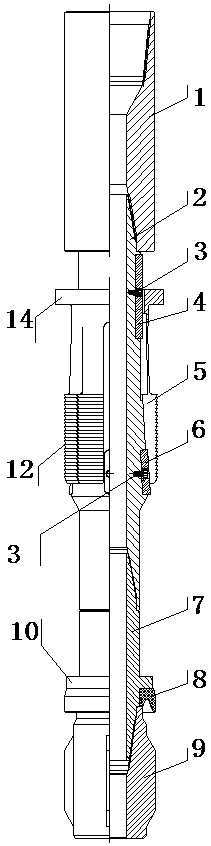
[0035] A guiding and locking mechanism suitable for casing drive heads, including a central shaft 2 and slips 5 sleeved on the central shaft 2, the central shaft 2 cooperates with the casing through the slips 5 for lifting, lowering and rotating casing.

[0036] In the present invention, the central shaft 2 includes a positioning section 11 and a driving section 13 from top to bottom. The positioning section 11 is fixedly provided with a positioning key 4, and the driving section 13 is fixedly provided with a driving key 6. The surface of the driving section 13 is conical. surface, and the diameter of the upper end is smaller than the diameter of the lower end.

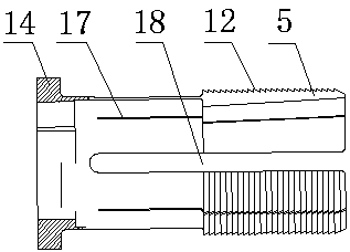
[0037] In the present invention, one end of the slip 5 is provided with a locking tooth 12 cooperating with the inner wall of the casing, and the other end is provided with a limiting keyway cooperating with the positioning key 4 for controlling the relative rotation range of the central shaft 2 and the slip 5 20. Th...

Embodiment 2

[0045] This embodiment illustrates the application of the present invention in the casing drive head:

[0046] The casing driving head includes a variable button joint 1, a guiding and locking mechanism, and a righting sealing mechanism;

[0047] The guiding and locking mechanism includes the central shaft 2, the positioning key 4, the slips 5, the driving key 6 and the lower joint 7. One end of the central shaft 2 is a male buckle, and the other end is a female buckle. The male buckle and the female buckle end of the central shaft 2 Positioning keyway 15 and driving keyway 16 are respectively provided with, positioning key 4 is arranged in positioning keyway 15, driving key 6 is arranged in driving keyway 16, positioning key 4 is fixed in positioning keyway 15 by fixing bolt 3, driving key 6 The fixed bolt 3 is fixed in the driving keyway 16; the slip 5 is set on the outer circle of the central shaft 2, and the slip 5 is a cylindrical structure, one end of the slip 5 is the s...

Embodiment 3

[0056] The present embodiment explains as follows to the operation method that adopts casing driving head of the present invention:

[0057] Before implementing casing drilling, prepare the required casing driving head first. During implementation, first connect the drill shoe and floating hoop at the lower end of the first casing that needs to be lowered into the well, and then use the single elevator on the drilling rig Lift the first casing that has been connected with drill shoes and floating hoops, put it into the wellbore, and use casing slips to clamp the first casing in the rotary table, and then connect the casing to the drilling tool drive head.

[0058] Then lower the drilling tool, insert the casing driving head into the first casing placed on the turntable, start the drilling rig, make the drilling tool turn right, and drive the casing driving head to turn right 45 degrees (just use 45 degrees as an example, not limited to 45 degrees), and then lift the drilling ...


PUM


Abstract

The invention discloses a guiding and locking mechanism suitable for a casing pipe driving head. The guiding and locking mechanism comprises a center shaft and a clamping tile, wherein the center shaft is sleeved with the clamping tile. The center shaft is used for lifting, dropping and rotating a casing pipe through matching of the clamping tile and the casing pipe. By adopting the clamping tile, due to a key groove of the clamping tile and a gap, a tool can be set for driving the casing pipe to rotate or a driving mechanism can be taken out according to needs, locking or unlocking between the tool or the driving mechanism and the casing pipe can be changed, and the mode of drilling through the casing pipe can be implemented conveniently. Clamping teeth have good adhesive force, can achieve locking with the underground casing pipe wall effectively and can be attached to the casing pipe wall after being inserted into the casing pipe, and therefore mutual swing between the casing pipe and the casing pipe driving mechanism can be reduced, the clamping teeth can be attached to the casing pipe inner wall closely when being connected with the casing pipe completely, and the effect of preventing the casing pipe from dropping can be achieved.

Description

technical field [0001] The invention relates to a guiding and locking mechanism suitable for a casing driving head, which is used for oil and gas drilling with casing, and belongs to the technical field of design and manufacture of drilling equipment. Background technique [0002] In the process of conventional oil and gas drilling, due to the geological characteristics of the formations in various places, downhole complex situations such as borehole diameter shrinkage, well wall collapse, keyway and lost circulation caused by drilling tools in drilling often occur. In this case, after the completion of drilling When implementing casing running and cementing rotation, some wells will encounter resistance and jamming, and some even have problems such as the casing cannot be lowered to the predetermined depth. When these situations occur, the construction will not meet the requirements of engineering design, and some There will also be safety accidents in the casing running pr...

Claims


Application Information

Patent Timeline
Patent Type & Authority Patents(China)
IPC IPC(8): E21B7/20E21B19/10
Inventor 李伟成陈晓彬陈立陈文才刘彬邓元洲胡畔周刚冯明
Owner BC P INC CHINA NAT PETROLEUM CORP
Why Eureka
Try Eureka