
Method for construction of diameter-expanding pile on pile top

A construction method and technology of expanding diameter piles, applied in sheet pile walls, foundation structure engineering, construction, etc., can solve problems such as thick and unfavorable sediment at the bottom of holes, and failure to meet the construction accuracy requirements of ultra-deep cast-in-situ piles

Inactive Publication Date: 2013-12-11
SHANGHAI MECHANIZED CONSTR GRP
View PDF5 Cites 3 Cited by
  • Summary
  • Abstract
  • Description
  • Claims
  • Application Information

AI Technical Summary

Problems solved by technology

Due to the use of GPS series rotary drilling rigs to form holes for traditional pile top expansion piles, it can only meet the requirement that the hole verticality deviation is within 1 / 200, and cannot meet the construction of ultra-deep cast-in-place piles with a hole verticality deviation within 1 / 500 Accuracy requirements; the GPS series rotary drilling rig is used to form the hole, and the sediment at the bottom of the hole is relatively thick, which increases the workload of hole cleaning; the existing pile top expansion pile is made into a stepped shape when the hole is formed at the variable section of the pile body. , it’s just that when the reinforcement cage is manufactured, a variable section with a slope is processed at the variable section, so the outer surface of the cast-in-place pile that is finally cast is not a variable section that meets the slope requirements, because the variable section is not moderate. In the transition section, due to the sudden change of stiffness in such a variable section, the stress concentration is relatively prominent, which is very unfavorable for pile top expansion piles with high requirements for horizontal force

Method used


Image

  • Method for construction of diameter-expanding pile on pile top
  • Method for construction of diameter-expanding pile on pile top
  • Method for construction of diameter-expanding pile on pile top

Examples


Embodiment Construction

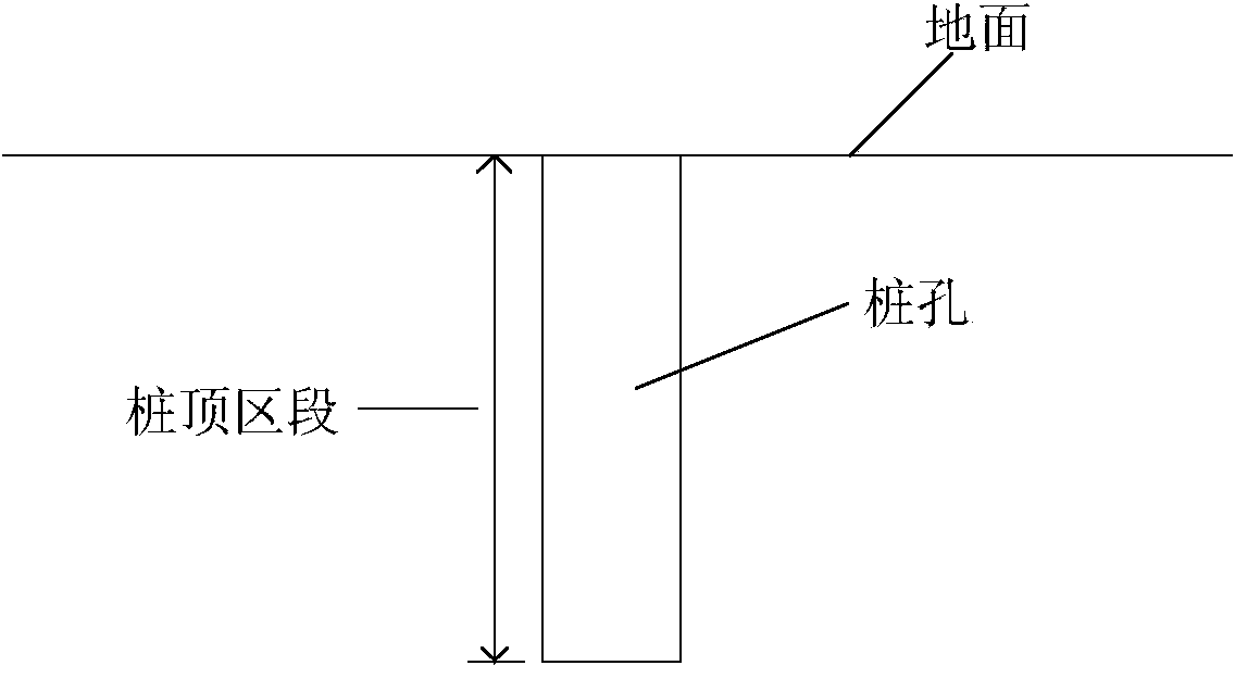
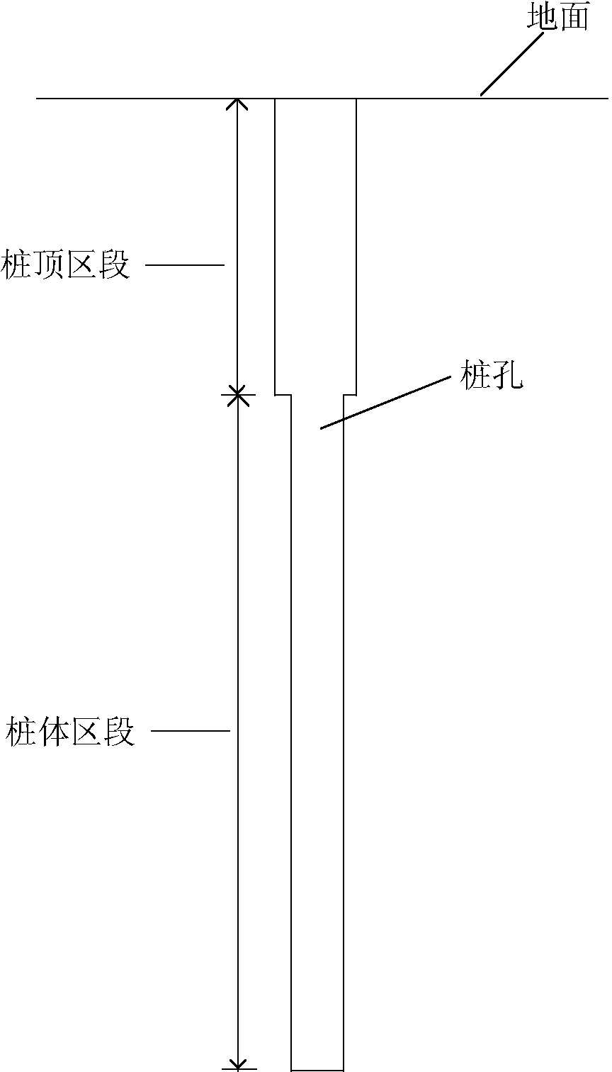
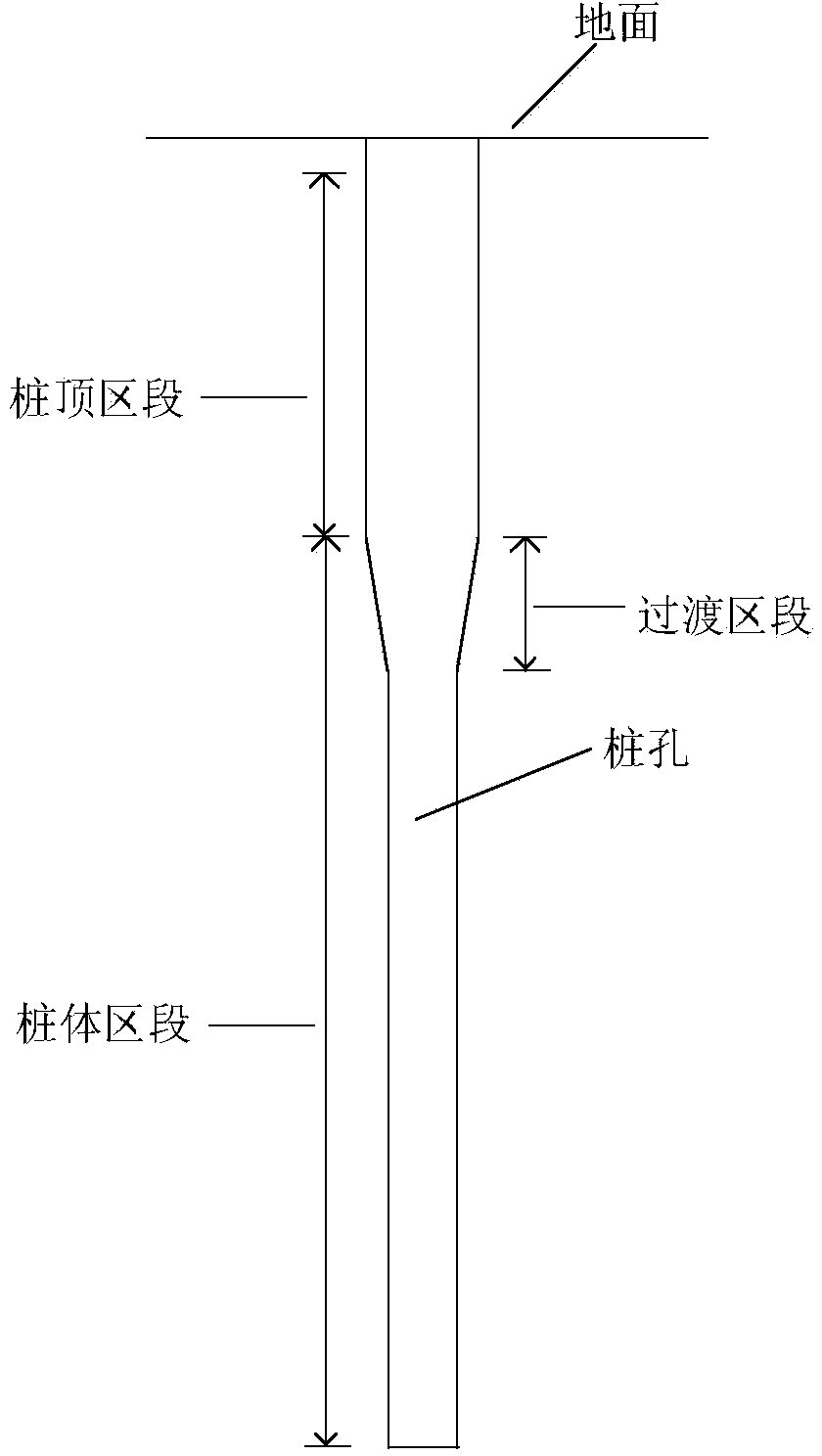
[0026] The following will combine Figure 1 to Figure 5 The construction method of the pile top diameter expansion pile provided by the present invention is described in detail, which is an optional embodiment of the present invention, and it can be considered that those skilled in the art can implement it within the scope of not changing the spirit and content of the present invention. Modify and polish.

[0027] The present embodiment provides a method for constructing pile top diameter-expanding piles, which includes the following steps in turn:

[0028] S10: Please refer to figure 1 , the rotary drilling rig is equipped with a large-diameter drill bit and then drilled on the ground to form an enlarged pile top section. At this time, the pile hole only includes the pile top section; in this step, drill from the ground to the variable section At the upper edge of the pile, this position matches the reinforcement cage made separately, and it can also be considered as the el...


PUM


Abstract

The invention provides a method for construction of a diameter-expanding pile on a pile top. The method at least includes the first step of enabling a rotary drilling rig to carry out hole-drilling construction on the ground after being provided with a large-diameter drill bit to form a diameter-expanded pile top section, the second step of enabling the rotary drilling rig to be provided with a small-diameter drill bit to drill at the bottom of the pile top section to pile bottom scale height so as to form a pile body section under the pile top section, the third step of enabling the rotary drilling rig to carry out finishing construction on the inner wall of the pile body section after being provided with a diameter variable drill bit to achieve slope connection at the joint between the pile body section and the pile top section so as to form a transition section enclosed by the slope structure in the pile body section, the fifth step of placing a reinforcement cage into a pile hole, wherein the shape of the reinforcement cage is matched with the that of the pile hole, and the seventh step of using a guide pipe method, and carrying out concrete pouring on the pile hole through the pouring concrete guide pipe until pouring of the pile top section is finished.

Description

technical field [0001] The invention relates to the field of civil engineering construction, in particular to a construction method for a pile top diameter expanding pile. Background technique [0002] The cast-in-situ pile system refers to the piles formed by forming pile holes in the foundation soil by means of mechanical drilling, steel pipe extrusion or manual excavation on the project site, and placing steel cages in them and pouring concrete. [0003] Compared with cast-in-situ piles with equal diameters, pile top expansion piles can effectively improve the horizontal resistance of single piles and reduce the vibration impact of traffic and pedestrian flow or subways while controlling the settlement of pile foundations, and can also save concrete consumption. Popularized in pile foundation engineering. Due to the use of GPS series rotary drilling rigs to form holes for traditional pile top expansion piles, it can only meet the requirement that the hole verticality dev...

Claims


Application Information

Patent Timeline
Patent Type & Authority Applications(China)
IPC IPC(8): E02D5/36E02D5/48
Inventor 陈晓明薛备芬冯琰张顺王恺华张冰黄炜焱胡怡郭捷夫
Owner SHANGHAI MECHANIZED CONSTR GRP
Learn More