
Improved heating lamp box for blow molding machine

A blow molding machine and light box technology, applied in the field of blow molding machine heating devices, can solve the problems of energy waste, uneven heating of plastic preforms, inability to heat plastic preforms, etc., and achieve the effect of improving heating quality

Inactive Publication Date: 2013-12-11
李伟宏
View PDF3 Cites 2 Cited by
  • Summary
  • Abstract
  • Description
  • Claims
  • Application Information

AI Technical Summary

Problems solved by technology

The existing heating device mainly includes a heating bracket, a lamp tube pole is installed on the heating bracket, a lamp tube clamp is installed on the head of the lamp tube pole, a heating lamp tube is installed on the lamp tube, and the heating lamp tube heats the plastic preform. Yes: Since the heating device is installed on one or both sides of the conveying mechanism, and the heating rod and the lamp clamp are fixed and cannot be adjusted, if the plastic preform is short, it will cause energy waste; on the other hand, the fixed lamp The support rod cannot be stretched and stretched, and the top of the plastic preform cannot be directly heated, which affects the rational use of energy and also leads to uneven heating of the plastic preform

Method used


Image

  • Improved heating lamp box for blow molding machine
  • Improved heating lamp box for blow molding machine
  • Improved heating lamp box for blow molding machine

Examples


Embodiment Construction

[0028] The present invention will be described in detail below in conjunction with the accompanying drawings.

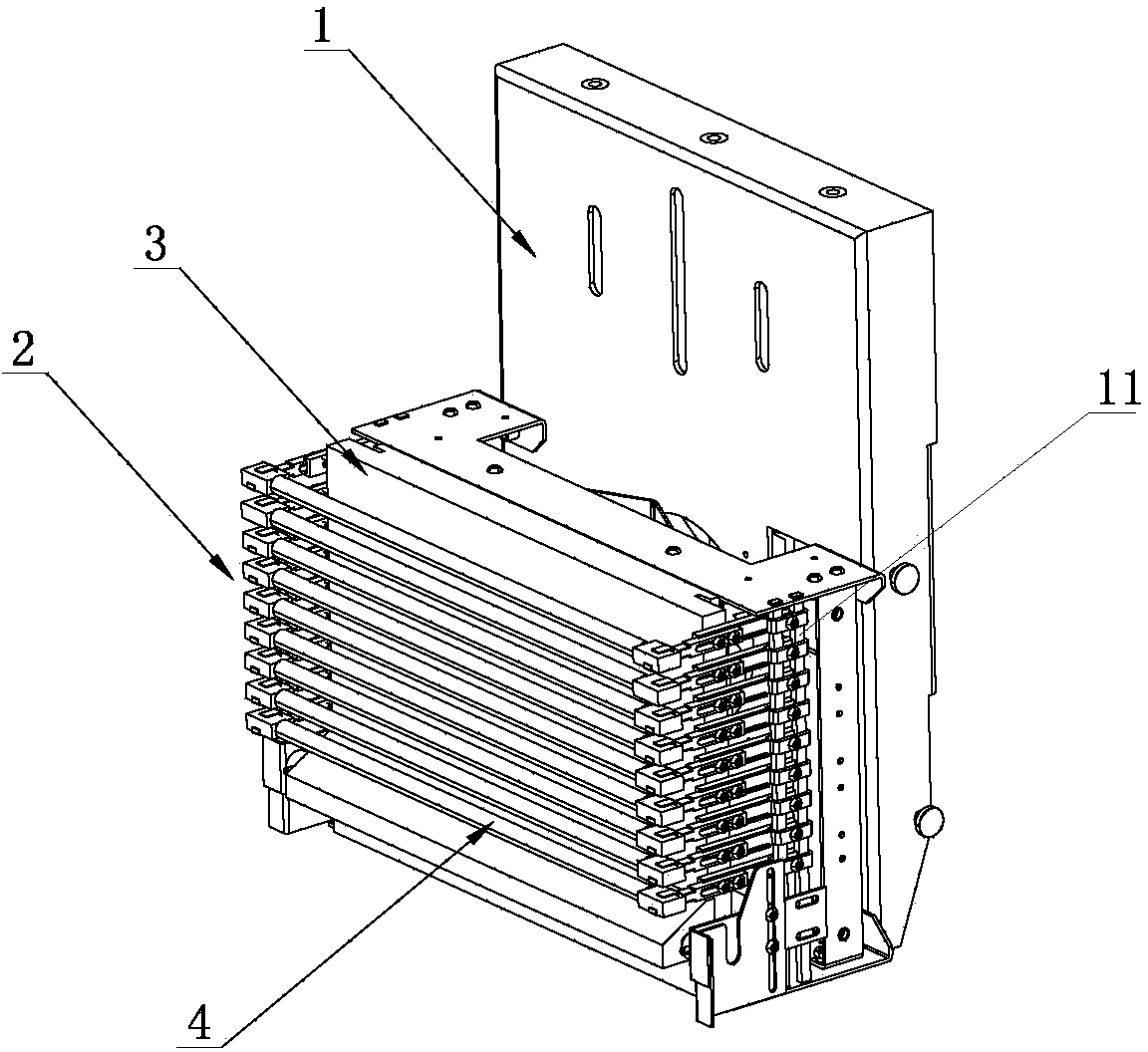
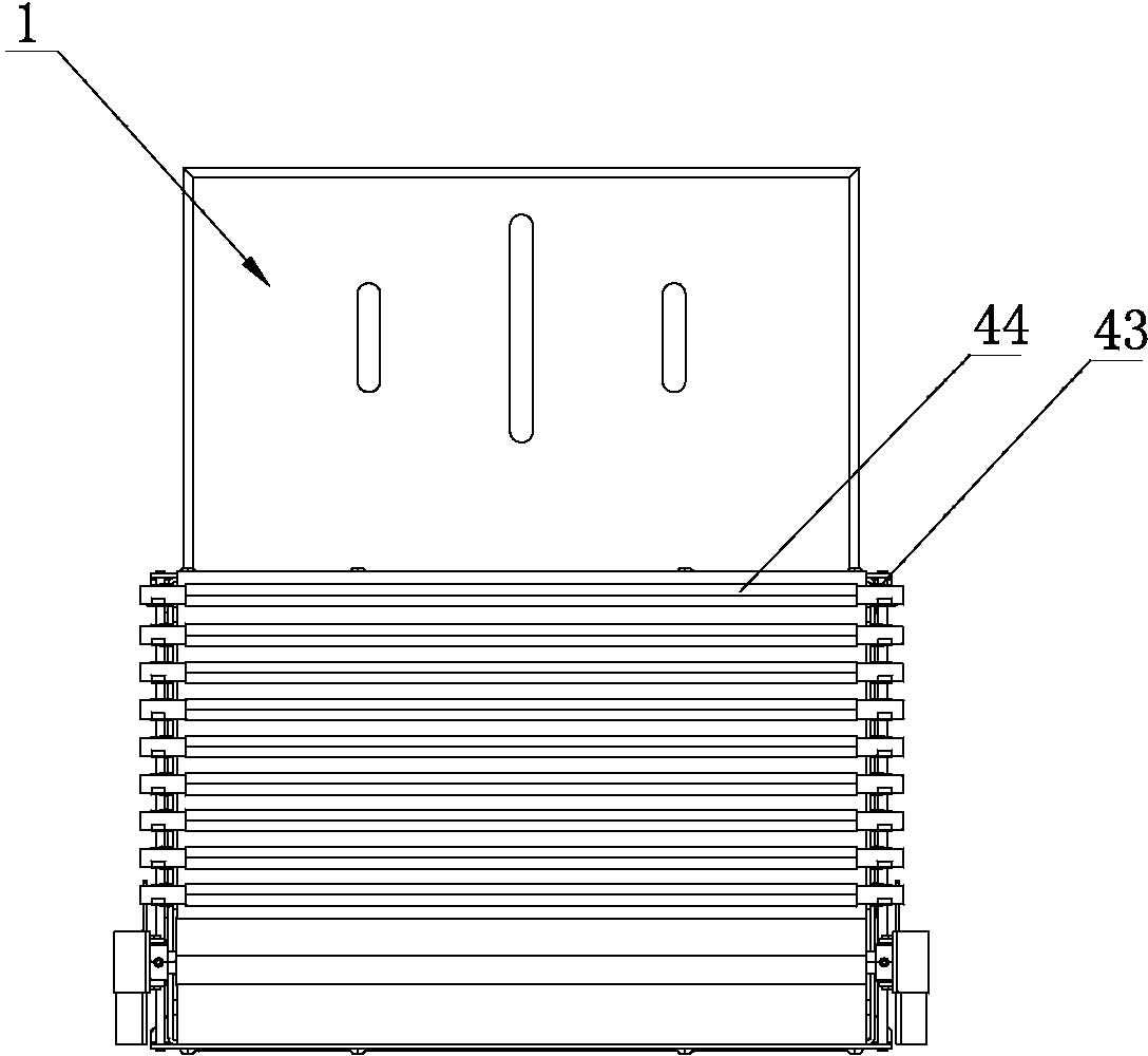
[0029] Such as Figure 1 to Figure 7 As shown, an improved blow molding machine heating light box of the present invention includes a light box frame 1, a heating device 2 is arranged at the front end of the light box frame 1, and a heat insulation board is arranged between the heating device 2 and the light box frame 1 3. The heating device 2 is composed of several heating components 4. The heating component 4 includes a longitudinal adjustment terminal 41, a horizontal adjustment terminal 42 and a heating lamp tube 44. The longitudinal adjustment terminal 41 is longitudinally slidably connected to the light box frame 1, the horizontal adjustment terminal 42 is horizontally slidably connected to the front end of the longitudinal adjustment terminal 41; the front end of the horizontal adjustment terminal 42 is connected with a lamp clamp 43, and the heating lamp 44 i...


PUM


Abstract

The invention relates to the technical field of a heating device for a blow molding machine, and in particular relates to an improved heating lamp box for a blow molding machine. The improved heating lamp box comprises a lamp box frame; a heating device is arranged at the front end of the lamp box frame; a heat insulation plate is arranged between the heating device and the lamp box frame; the heating device consists of a plurality of heating components; each heating component comprises a longitudinal adjusting terminal, a transverse adjusting terminal and a heating lamp tube; the longitudinal adjusting terminals are connected with the front end of the lamp box frame in a longitudinal sliding way; the transverse adjusting terminals are connected with the front ends of the longitudinal adjusting terminals in a transverse sliding way; the front ends of the transverse adjusting terminals are connected with lamp tube clamps; the heating lamp tubes are arranged in the lamp tube clamps. Longitudinal distance adjustment and transverse distance adjustment are realized by the longitudinal adjusting terminals and the transverse adjusting terminals respectively, so that the distances between the heating lamp tubes and plastic bottle blanks can be adjusted, and the distances among the heating lamp tubes also can be adjusted; therefore, the heating quality of the plastic bottle blanks can be improved, the plastic bottle blanks are evenly heated, and the blow molding quality of the plastic bottle blanks can be improved.

Description

technical field [0001] The invention relates to the technical field of blow molding machine heating devices, in particular to an improved blow molding machine heating light box. Background technique [0002] Before the plastic bottle is blow-molded, a heating device is required to heat the plastic preform. After the plastic preform becomes soft, the conveying mechanism will send the plastic preform to the blow molding machine for blow molding. The existing heating device mainly includes a heating bracket, a lamp tube pole is installed on the heating bracket, a lamp tube clamp is installed on the head of the lamp tube pole, a heating lamp tube is installed on the lamp tube, and the heating lamp tube heats the plastic preform. Yes: Since the heating device is installed on one or both sides of the conveying mechanism, and the heating rod and the lamp clamp are fixed and cannot be adjusted, if the plastic preform is short, it will cause energy waste; on the other hand, the fixed...

Claims


Application Information

Patent Timeline
IPC IPC(8): B29C49/64B29C49/78
Inventor 李伟宏
Owner 李伟宏
Learn More