
A two-finger translational manipulator

A manipulator and translation technology, applied in the field of robotics, can solve problems such as difficulty in grasping workpieces that are too large or too small, difficulty in adjusting the distance between finger roots, high requirements for installation and use, and achieve simple structure, strong adaptability, The effect of enhancing the ability to grasp workpieces

Active Publication Date: 2015-10-21
ZHEJIANG UNIV
View PDF8 Cites 1 Cited by
  • Summary
  • Abstract
  • Description
  • Claims
  • Application Information

AI Technical Summary

Problems solved by technology

At present, some manipulators in my country adopt a simple rotating shaft finger design, such as "a pneumatic mechanical hand claw" disclosed in 201120367424. Opening and closing, but it is difficult to adjust the distance between the bases of the fingers with rotating shaft movement, so it is difficult to grasp workpieces that are too large or too small, and the scope of application is limited to a certain extent; some robots adopt the design of adjustable grip distance , such as 201220191296's "manipulator with adjustable claw spacing", that is, an adjusting screw is used in the design to adjust the distance between the first gripper and the second gripper, so as to realize the grasping of workpieces of different sizes
However, this type of manipulator is expensive and has high requirements for installation and use.

Method used


Image

  • A two-finger translational manipulator
  • A two-finger translational manipulator
  • A two-finger translational manipulator

Examples


Embodiment Construction

[0013] Further illustrate the present invention below in conjunction with accompanying drawing.

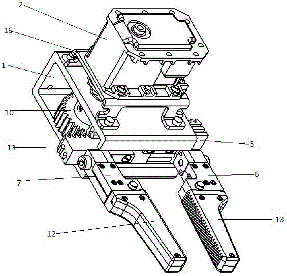
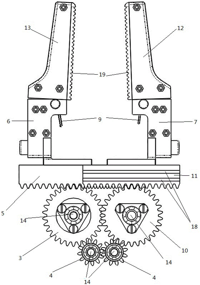
[0014] refer to Figure 1-Figure 5 , the structure of the two-finger translation manipulator of the present invention includes: palm base 1, steering gear 2, left finger gear 3, two transmission gears 4, left finger translation rack 5, left finger root 6, right finger root 7 , two micro switches 8, two recovery springs 9, right finger gear 10, right finger translation rack 11, right finger 12, left finger 13, four gear shafts 14, steering frame 16, rubber skin 19 and balls bearing 20.

[0015] Servo 2 (see figure 1 ) is installed above the palm base 1 through the steering rack 16, and the palm base 1 (see Figure 6 ) There are two horizontally protruding rack guide rails 17 on the upper and lower inner surfaces of the front part, and there are two transversely recessed teeth on the lower plane of the left finger translation rack 5 and the upper plane of the right finger transla...


PUM


Abstract

The invention discloses a two-finger translation mechanical arm which comprises a palm base, a steering engine, transmission gears, translation racks, a left finger and a right finger, wherein the steering engine is arranged above the palm base; an output shaft of the steering engine is respectively meshed with the translation racks by the two pairs of transmission gears, and the translation racks are respectively connected with the left finger and the right finger; when the steering engine rotates forward, the left finger and the right finger are separated from each other along with the translation racks; when the steering engine rotates backward, the left finger and the right finger are closed together along with the translation racks. The left finger and the right finger are respectively and internally provided with a reset torsion spring and a small microswitch; when a workpiece is clamped by the mechanical arm, the microswitches are touched, and information is fed back to a control system. The two-finger translation mechanical arm is simple in structure, high in sensitivity and convenient to install. When the workpiece is clamped by the left finger and the right finger, the microswitches arranged in the fingers are connected; the microswitches are disconnected in time when the workpiece is loosened; the motion state of the translation mechanical arm is fed back into the control system in time, so that the control system can sensitively judge the working state of the mechanical arm, and real-time control performance of the two-finger translation mechanical arm can be guaranteed.

Description

technical field [0001] The invention belongs to the technical field of robots, and in particular relates to a two-finger translational manipulator mechanism. Background technique [0002] In recent years, with the development of robot technology, people have put forward higher requirements for the reliability and real-time perception ability of manipulators. For the two-fingered manipulator, how to realize the fast grasping and sensitive perception of the manipulator has become a research hotspot in the field of robotics. Due to the complex working environment of the manipulator, there are many factors that affect its working state, and the key factor for realizing real-time control of the two-finger translational manipulator is whether the manipulator can be sensitive to whether the finger is in contact with the workpiece. At present, some manipulators in my country adopt a simple rotating shaft finger design, such as "a pneumatic mechanical hand claw" disclosed in 2011203...

Claims


Application Information

Patent Timeline
Patent Type & Authority Patents(China)
IPC IPC(8): B25J15/08
Inventor 朱秋国赵逸栋熊蓉褚健
Owner ZHEJIANG UNIV
Learn More