
Method for determining intermittent pumping system through oil-well pump dynamic fullness well testing

A technology of oil well pump and fullness, which is applied in the field of well testing of rod pump oil wells, and can solve the problems of high price, difficult matching, and failure of pumping control technology to apply to oil production, etc.

Active Publication Date: 2013-12-04
王双全
View PDF10 Cites 24 Cited by
  • Summary
  • Abstract
  • Description
  • Claims
  • Application Information

AI Technical Summary

Problems solved by technology

First, the method is cumbersome. The net stroke measurement and mechanical control software of the oil well pump embedded in the vacuum control device adopted in the United States is expensive, and it is not easy to match with the controller manufacturer
The second is that the method only gives how to calculate the net stroke value of the oil pump by calculating the indicator diagram and the pump diagram, and determine the parameters for stopping the pumping, but does not give the judging parameters for how long it takes to stop the pumping before starting the pumping
As a result, the vacuum control technology cannot be applied to the actual oil production

Method used


Image

  • Method for determining intermittent pumping system through oil-well pump dynamic fullness well testing
  • Method for determining intermittent pumping system through oil-well pump dynamic fullness well testing
  • Method for determining intermittent pumping system through oil-well pump dynamic fullness well testing

Examples


Embodiment

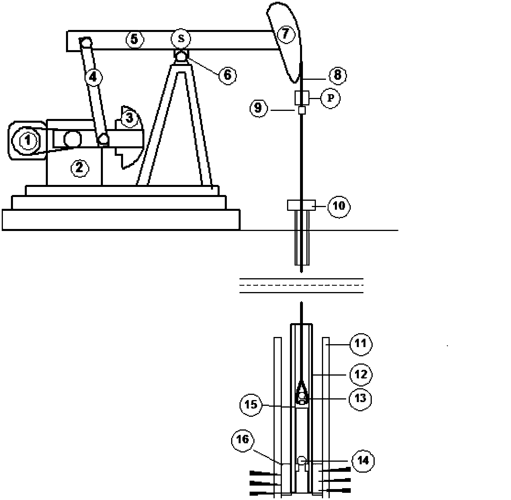
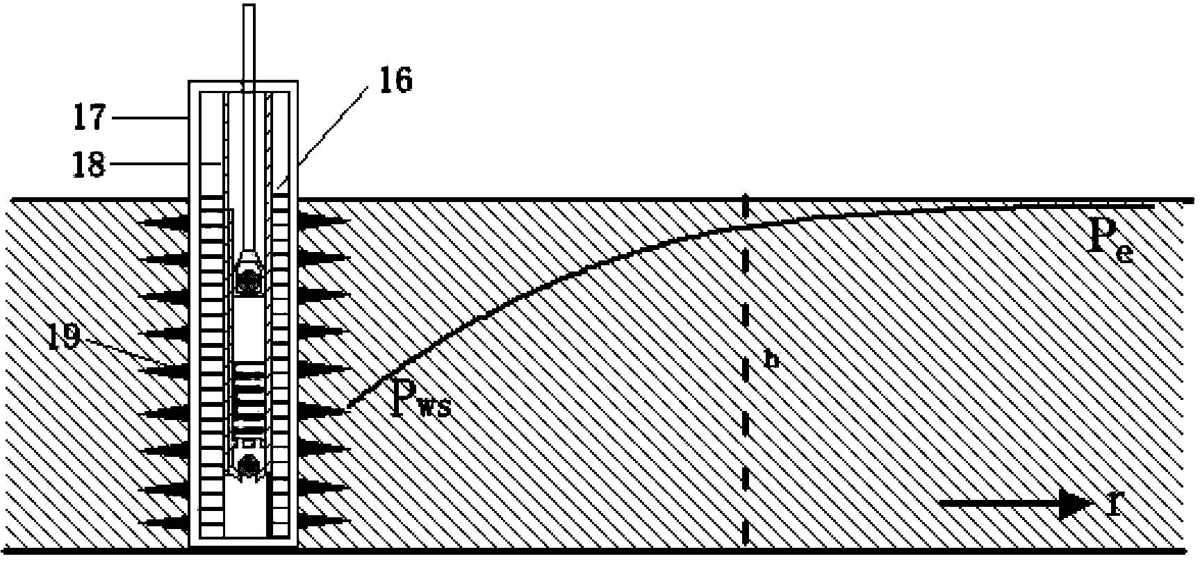
[0075] In this embodiment, the test procedure and steps of the dynamic oil well pump fullness test to determine the best intermittent pumping system method are as follows Figure 8 shown. details as follows:

[0076] 1. Test the fullness of the oil well pump.

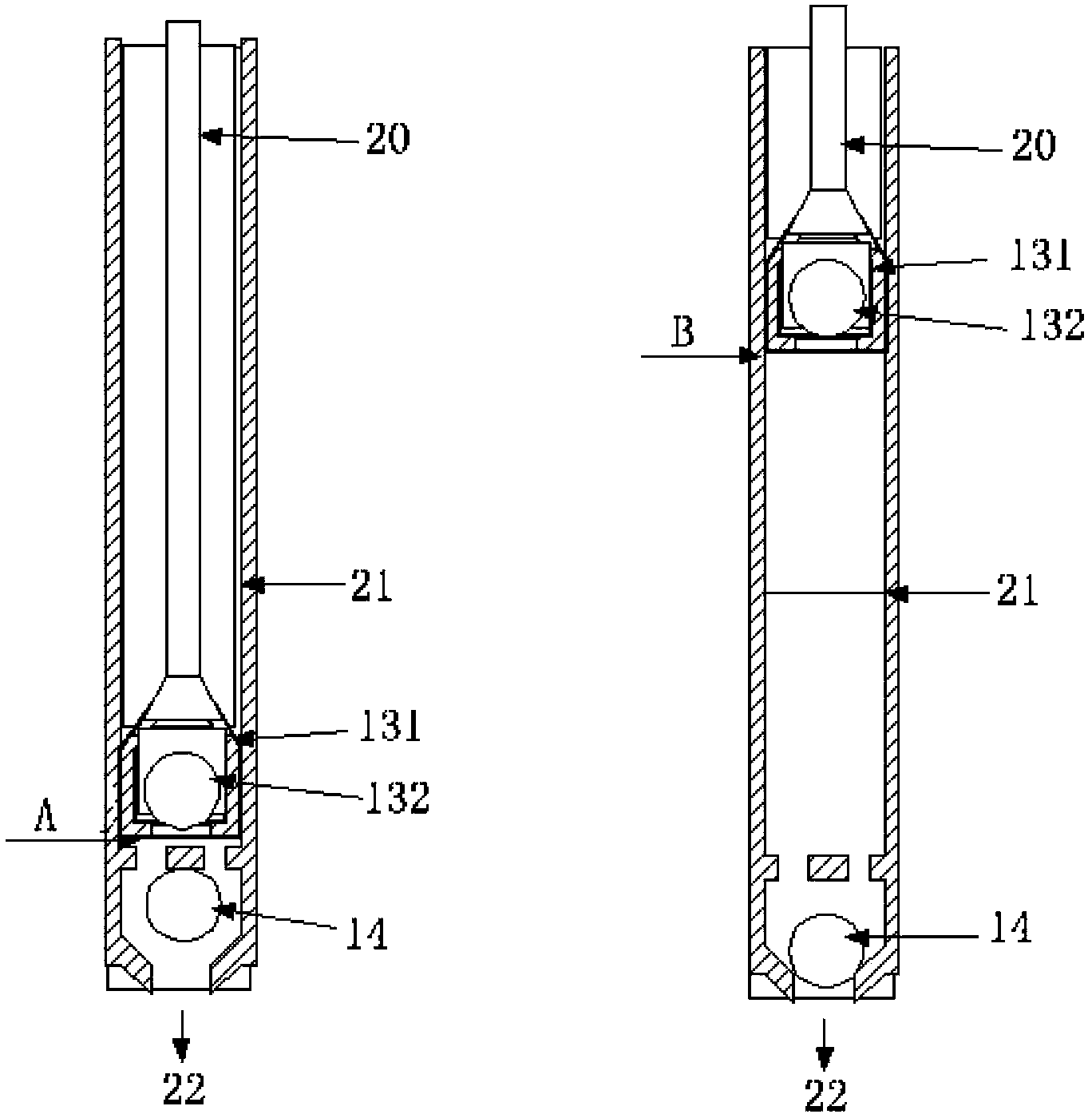
[0077] The test of the fullness of the oil pump is firstly used figure 1 The light rod load sensor on point P and the angular displacement sensor on point S in the middle measure the load-time curve and displacement-time curve. The shape of the measured curve is as Figure 5shown. In the displacement-time curve, point A is the bottom dead center, and point B is the top dead center. The load-time curve is an irregular motion curve, but there are two characteristic points on the load-time curve, namely point C and point D. Point C is when the piston moves upward from the bottom dead center until the pressure in the well pump is less than the bottom hole pressure and the opening point of the fixed valve. The positio...


PUM


Abstract

The invention discloses a method for determining an intermittent pumping system through oil-well pump dynamic fullness well testing. The method for determining the intermittent pumping system through oil-well pump dynamic fullness well testing comprises the steps of (1) determining a net stroke of a piston of an oil-well pump through synchronous measurement of a continuous polish rod load-and-time curve and a polish rod continuous displacement-and-time curve, and using a percentage between the net stroke and a gross stroke as a fullness measuring value; (2) building a complete oil-well pump dynamic fullness decreasing history curve according to continuous read and continuous analysis of the fullness, and obtaining an etamax and an etac according to the complete oil-well pump dynamic fullness decreasing history curve; (3) using the time spent by the process that the fullness of an oil well with the given characteristic decreases from the etamax to the etac as a fixed pumping time, and selecting different to-be-pumped times Tg to form an intermittent period; (4) using a percentage between the fixed pumping time and a well shutdown time as a pumping duty ratio, compiling a series of intermittent pumping systems according to different period systems, and determining an optimum intermittent pumping system according to the maximum daily output method and a minimum pumping duty ratio. The method for determining the intermittent pumping system through oil-well pump dynamic fullness well testing enables a sucker-rod pumping oil well to achieve maximum capacity, and reduces energy consumption and operating cost.

Description

technical field [0001] The invention relates to the technical field of well testing methods for rod pumped oil wells, in particular to a method for determining intermittent pumping regimes through dynamic fullness testing of oil well pumps. Background technique [0002] Rod pumps have been used in onshore oil extraction technology for pumping (Pumping) for more than 150 years. The current stage of onshore oil exploration and development shows that the underground oil reservoirs in old oilfields have serious pressure decline, and the bottom hole pressure can provide the ability to fill the oil well pumps. Low-permeability oil layer, the ability to supply liquid to the bottom of the well is also not enough to fill the well pump. The design of the mechanical oil pumping system is limited by the physical conditions of the minimum size, resulting in a serious disharmony between the high pumping capacity and the low bottom-hole fluid supply capacity. Such an oil pumping well wil...

Claims


Application Information

Patent Timeline
IPC IPC(8): E21B47/009F04B49/00
Inventor 王双全
Owner 王双全
Learn More