Safety door device of injection moulding machine

An injection molding machine, safety door technology, applied in the field of safety door devices, can solve problems such as cost increase

Active Publication Date: 2015-03-25
FANUC LTD
View PDF6 Cites 0 Cited by
  • Summary
  • Abstract
  • Description
  • Claims
  • Application Information

AI Technical Summary

Problems solved by technology

However, as the size of the machine increases, the safety door attached to the machine also becomes larger. Therefore, if the safety door is configured to rotate horizontally using hinges, a wide space is required around the machine to allow the rotation.
Also, hinges for rotation of the safety door require a strong structure capable of withstanding the weight of the safety door, resulting in increased cost

Method used


Image

  • Safety door device of injection moulding machine
  • Safety door device of injection moulding machine
  • Safety door device of injection moulding machine

Examples


Embodiment Construction

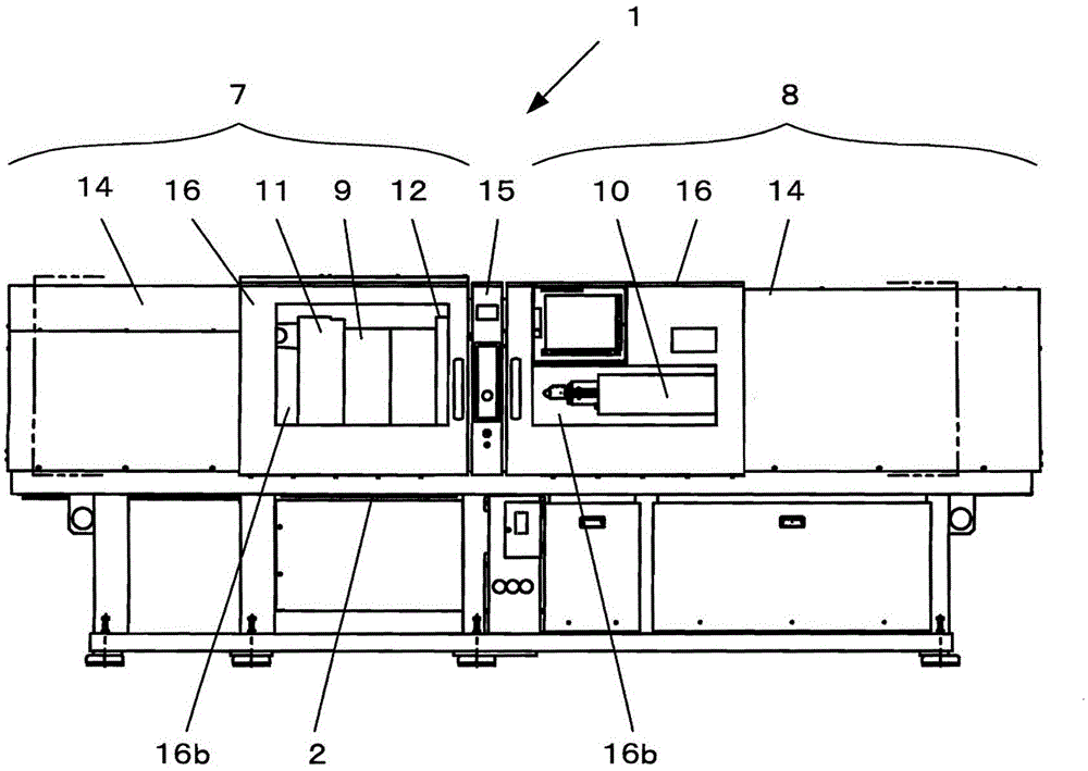
[0031] use figure 1 An injection molding machine equipped with the safety door device of the present invention will be described.

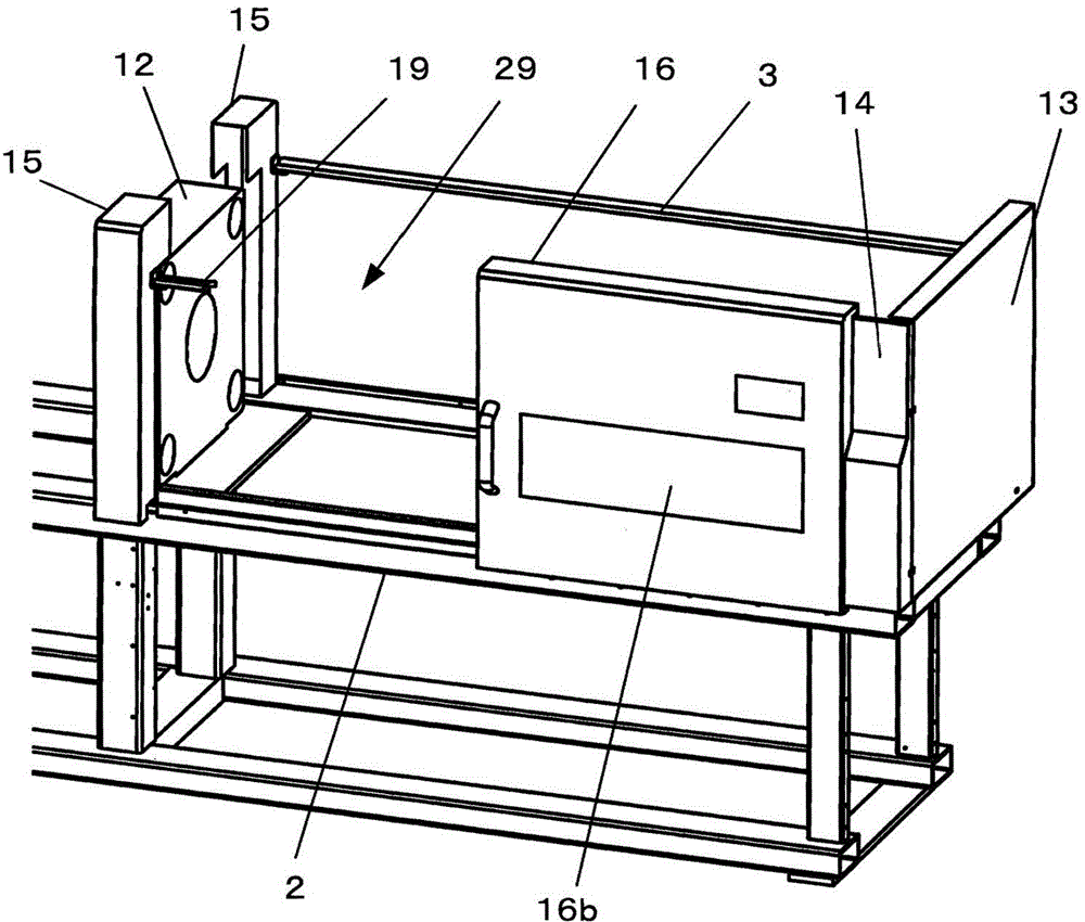
[0032] The injection molding machine 1 is composed of a mold clamping unit 7 and an injection unit 8 . The clamping part 7 and the injection part 8 are arranged opposite to each other on the machine base, and each has a plurality of mechanical driving parts, and the movement of each part is strong and high-speed, which may bring danger to the operator, so the fixing of the end parts Cover 13 (refer to figure 2), the fixed cover 14 on the side and other covers, so as to isolate it from the workers. In addition, reference numeral 15 denotes a fixed shelf cover covering the fixed shelf 12 .

[0033] In the replacement of the mold 9, the replacement of the cylinder part 10, etc., it is necessary to provide the clamping space (between the movable shelf 11 and the fixed shelf 12) of the mold clamping part 7, and the space for the rotation axis (bet...


PUM


Abstract

The invention provides a safety door device for an injection molding machine. The safety door of the injection molding machine is supported by the upper rail and the lower rail so that sliding in the horizontal direction is possible. The upper guide rail is divided into two into a front guide rail and a rear guide rail to improve the workability of the operator. The first and second rollers of the safety door are respectively supported on the front and rear guide rails, and especially the second roller is always supported by the rear guide rail.

Description

technical field [0001] The invention relates to a safety door device of an injection molding machine. Background technique [0002] The injection molding machine consists of a mold clamping section and an injection section. In the mold clamping section, a mold is mounted on a laminate, and the mounted mold is opened and closed at a predetermined force and speed. In the injection section, resin pellets are melt-kneaded and the molten resin is injected into a mold. [0003] When installing the mold on the laminate, when taking out the molded product from the mold manually, when replacing the cylinder part of the injection part, when supplying resin pellets to the injection part, and when maintaining and repairing the clamping part and the injection part It is necessary to be able to access the mold clamping part and the injection part from the outside. [0004] However, since the mold is opened and closed in the mold clamping section, and the molten resin is injected at hig...

Claims


Application Information

Patent Timeline
Patent Type & Authority Patents(China)
IPC IPC(8): B29C45/84
CPCB29C45/84
Inventor 牧育广西村浩一
Owner FANUC LTD
Why Eureka
Try Eureka