Method for locating ultrahigh circular sand core

A positioning method and annular technology, applied in the direction of cores, casting equipment, casting molds, etc., can solve the problems of increased core gap, inaccurate positioning of sand cores, and difficulty in lowering cores, and achieves accurate relative size and guarantee. Dimensional accuracy, the effect of improving the efficiency of the core

Active Publication Date: 2013-12-04
KOCEL STEEL
View PDF6 Cites 5 Cited by
  • Summary
  • Abstract
  • Description
  • Claims
  • Application Information

AI Technical Summary

Problems solved by technology

Using this kind of positioning, there are certain defects in the process of core setting and box assembly: 1) The positioning method of the bottom positioning platform is adopted. The positioning platform is at the bottom of the sand core, and the height of the sand core exceeds 2000mm. It is inconvenient for the operator to observe the core setting process during the core setting process. The result of core setting cannot be accurately checked; 2) The sand core positioning table is at the bottom of the sand core. The operator can observe the whole process of the core setting process, but when the height of the sand core is greater than 2000mm, the sand core is not stable, and the positioning platform and the positioning groove at the side of the sand core are easy to get stuck, resulting in damage to the positioning platform and difficulty in setting the core
[0003] So far, there is no way to overcome the above drawbacks

Method used


Image

  • Method for locating ultrahigh circular sand core
  • Method for locating ultrahigh circular sand core
  • Method for locating ultrahigh circular sand core

Examples


Embodiment Construction

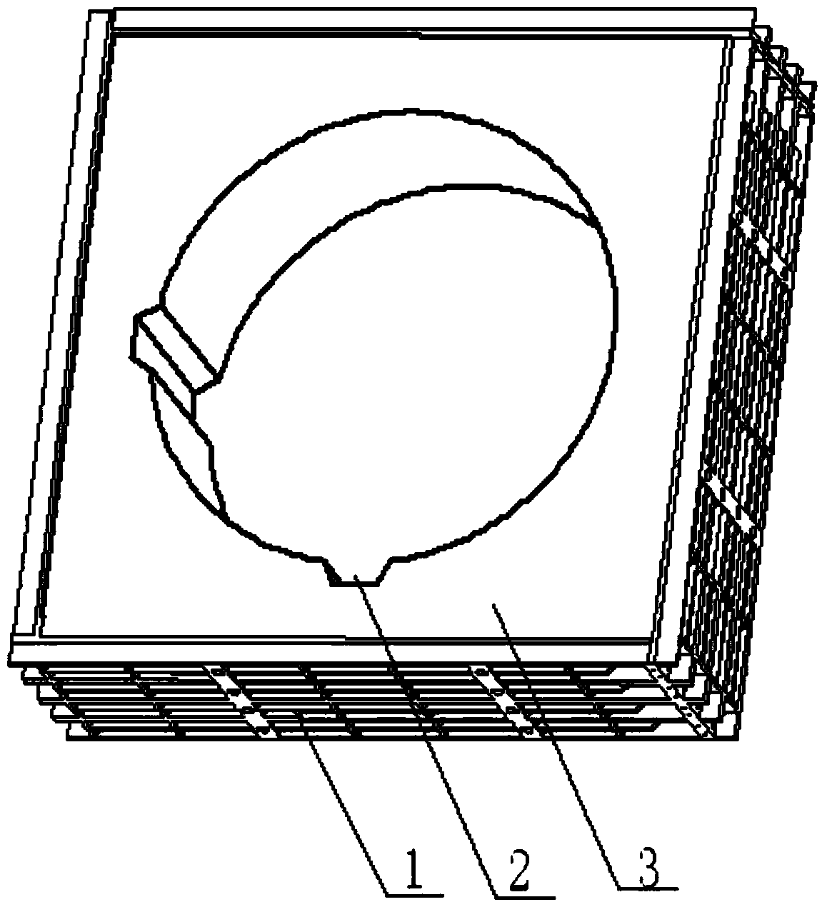
[0025] Such as figure 1 , 2 , 3, and 4 show:

[0026] A super-high annular sand core positioning method, the method includes the following steps:

[0027] a. Prepare two guide rods 7 having the same shape as the cavity positioning groove;

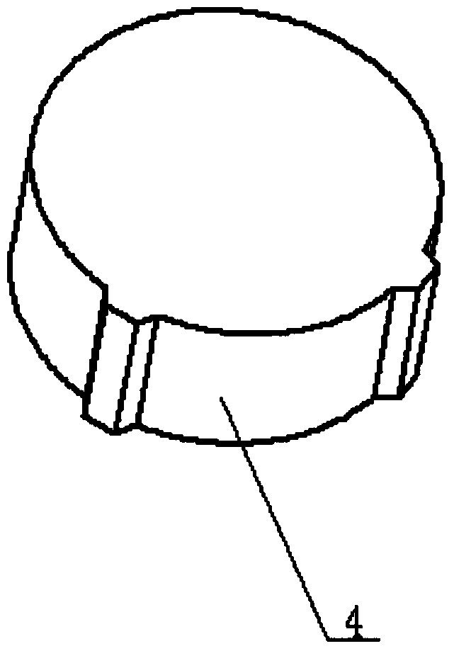
[0028] b. Place the pattern 4 with the same shape as the mold cavity in the sand box 1, adjust the position, and flow molding sand into the sand box 1;

[0029] c. After the molding sand is hardened, the shape is raised to form the cavity 3 and cavity positioning groove 2;

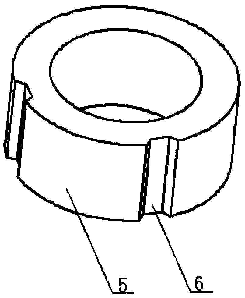
[0030] d, preparing a sand core 5 with a positioning groove 6;

[0031] e. In the cavity 3, place the guide rod 7 along the positioning groove 2 of the cavity;

[0032] f. Make the positioning groove 6 of the sand core correspond to the guide rod 7, and start to set the core along the guide rod 7. There is no need to adjust the sand core to match the cavity, and the sand core size is accurate;

[0033] g. After the core setting is completed, the guide rod 7 is li...


PUM

PropertyMeasurementUnit
heightaaaaaaaaaa

Abstract

The invention relates to a method for locating a ring product, a sand core, in particular to a method for locating an ultrahigh circular sand core. The method comprises the following steps that two guide rods with the shapes the same as the shapes of mold cavity locating grooves are manufactured; a die sample with the shape the same as that of a mold cavity is placed in a sand box, the position is adjusted well, and molding sand flows into the sand box; after the molding sand is hardened, the die sample is lifted out to form the mold cavity and the mold cavity locating grooves; a sand core body with locating grooves is manufactured; in the mold cavity, the guide rods are placed along the mold cavity locating grooves; the sand core locating grooves are made to correspond to the guide rods, and core setting is started along the guide rods; after the core setting is completed, the guide rods are lifted out, and the cavities defined by the mold cavity locating grooves and the sand core locating grooves are filled with the molding sand. The method is unique, and through the method of adopting the guide locating rods, in the core setting process, the operation is convenient, and the problem of locating damage is avoided.

Description

technical field [0001] The invention relates to a method for locating sand cores of ring products, in particular to a method for locating ultra-high circular sand cores. Background technique [0002] At present, for ultra-high ring products, the core molding method is usually used in the sand casting process. The molding sand outer cavity is composed of multiple sand cores, and the sand cores and the outer cavity are fixed and positioned by the positioning core head to ensure the accuracy of the casting process and the size of the core. The traditional sand core fixing method uses the bottom positioning platform or the side positioning platform for positioning. Using this kind of positioning, there are certain defects in the process of core setting and box assembly: 1) The positioning method of the bottom positioning platform is adopted. The positioning platform is at the bottom of the sand core, and the height of the sand core exceeds 2000mm. It is inconvenient for the ope...

Claims


Application Information

Patent Timeline
Patent Type & Authority Applications(China)
IPC IPC(8): B22C9/10
Inventor 杨建周催佰王新军罗永建郭小强鲁云
Owner KOCEL STEEL
Why Eureka
Try Eureka