Continuous composite stamping die

A technology for stamping dies and mold shells, applied in the field of continuous composite stamping dies, which can solve the problems of continuous stamping, time-consuming, and cumbersome problems

Active Publication Date: 2013-12-04
信阳汉华光电科技有限公司
View PDF6 Cites 4 Cited by
  • Summary
  • Abstract
  • Description
  • Claims
  • Application Information

AI Technical Summary

Problems solved by technology

[0003] The stamping dies of the prior art have the following defects: each time a screw is punched, five steps of mold opening, loading, stamping mold clamping, mold opening, and demoulding need to be carried out separately, and as many screws as needed to be stamped need to be repeated as many times as necessary. The speed is slow and the efficiency is low, and continuous stamping and forming cannot be performed; secondly, because the round bar is placed between the upper mold and the lower mold when discharging, in this way, if the mold opening range is too small before discharging and when the mold is opened, two The distance between the molds is not enough, it is difficult for people to put the round rod in, but if the mold opening range is too large, the stroke of the punch will be increased when the mold is opened and closed, which will consume more time and further reduce the efficiency. There is a certain risk of feeding between the two molds. In case the punch is accidentally started, it may hurt the hands; moreover, because the opening of the lower mold is upward, the demoulding process is too inconvenient; in addition to the above defects, the prior art There is still a huge defect in the stamping die of the company. A set of stamping dies can only be punched once and processed to form a screw of one shape. The five processes of hexagonal hole, chamfering, and shaping can be finally formed. Then, five sets of stamping dies must be used to repeat five times the process of mold opening, loading, stamping mold clamping, mold opening, and demoulding. cumbersome and inefficient

Method used


Image

  • Continuous composite stamping die
  • Continuous composite stamping die
  • Continuous composite stamping die

Examples


Embodiment Construction

[0017] The present invention will be further described below in conjunction with the accompanying drawings and specific embodiments.

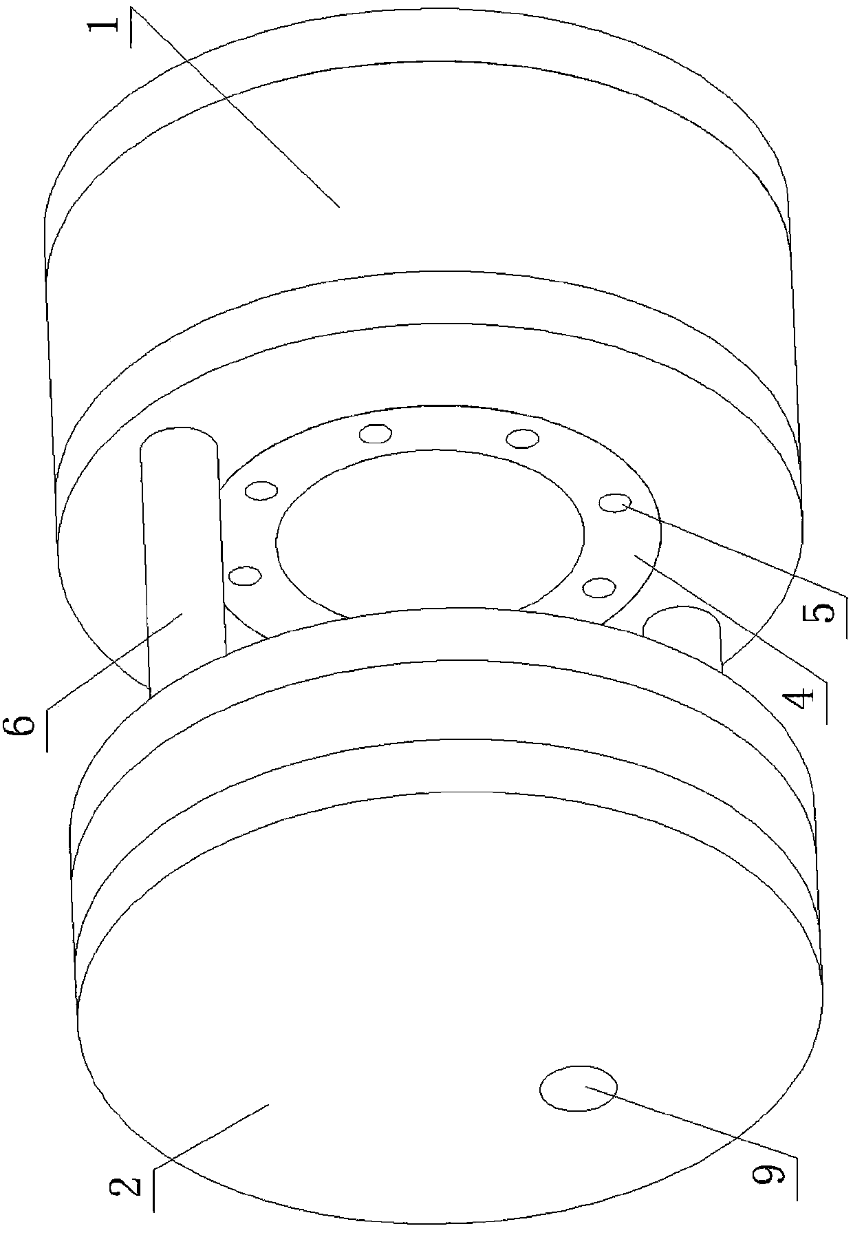
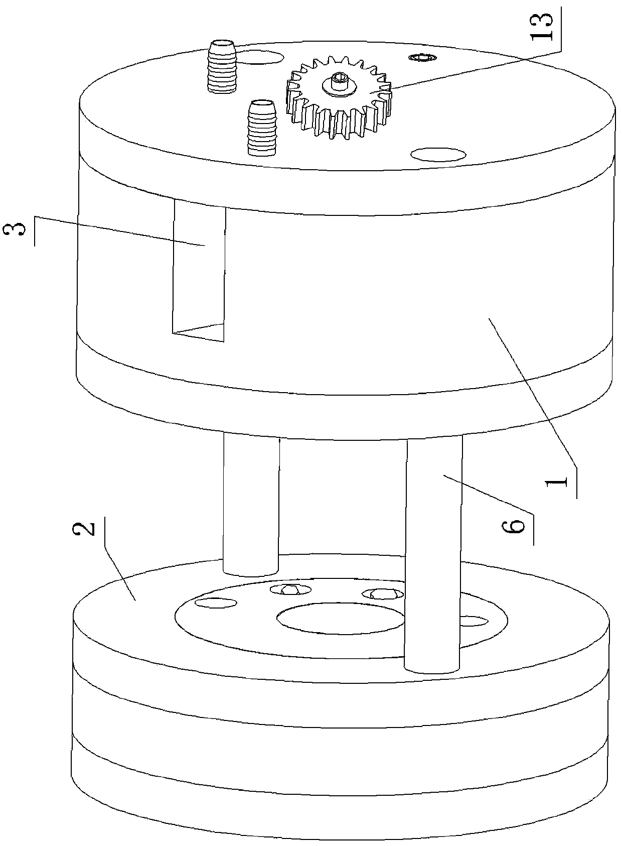
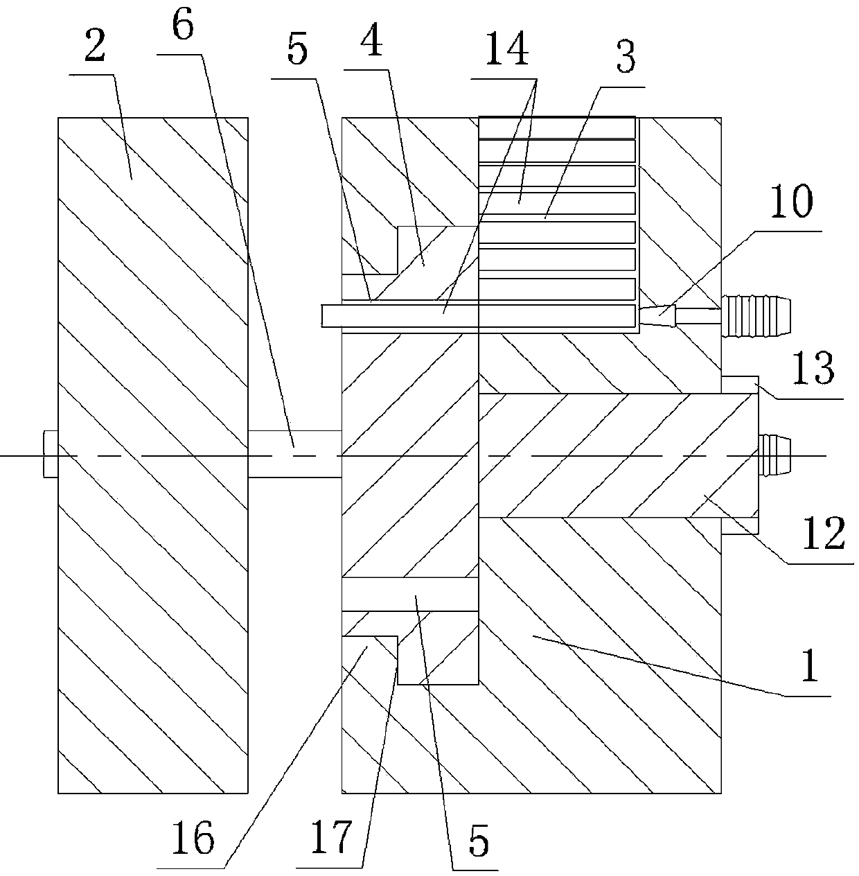
[0018] Such as figure 1 , figure 2 , image 3 , Figure 4 , Figure 5 , Figure 6 As shown, the continuous composite stamping die of the present invention includes a cylindrical formwork 1 and a punch 2 . The cylindrical formwork 1 is provided with a radial blanking channel 3 whose opening is located on the outer peripheral surface. The front end surface of the cylindrical formwork 1, that is, the end surface close to the punch 2, is provided with a cylindrical pit, and a turntable 4 is rotatably fitted in the cylindrical pit. Specifically, the opening of the cylindrical pit is provided with a limit ring 16, and the circumferential surface of the turntable 4 is provided with a limit step 17 against the limit ring 16, and the limit step 17 prevents the turntable 4 from breaking away from the cylindrical pit. . The front end face of the ...


PUM


Abstract

The invention discloses a continuous composite stamping die which comprises a cylindrical die case (1) and a punch pin (2). A radial blanking channel is formed in the cylindrical die case (1), a rotary table (4) which is in running fit with the cylindrical die case (1) is arranged in the cylindrical die case (1), a plurality of round through holes (5) are formed in the rotary table (4), a screw head portion cavity (7), a punching hexagonal socket hole cavity, an expansive hexagonal socket hole cavity, a chamfer cavity, a calibrator cavity and a discharging hole (9) are sequentially arranged on the same circumference of the end face, close to the cylindrical die case (1), of the punch pin (2), the discharging hole (9) penetrates through the punch pin (2) in the axial direction, the lowest end of the radial blanking channel is communicated with one round through hole (5), and the other six round through holes directly face towards the above five cavities and the discharging hole (9) one to one respectively. The continuous composite stamping die enables stamping processes to be fast, efficient, safe and convenient.

Description

technical field [0001] The invention relates to the technical field of dies, in particular to a continuous compound stamping die for stamping screws. Background technique [0002] The stamping die of the traditional stamping screw includes a lower die and an upper die. The upper end of the lower die is provided with a blind hole that matches the shape of the screw, that is, the lower die cavity. The lower end of the upper die is provided with cylindrical pits. The top is provided with hexagonal prism protrusions, and the cavity between the cylindrical recess and the hexagonal prism protrusions constitutes an upper die cavity that matches the shape of the head of the hexagon socket head screw, and the centerlines of the upper and lower die cavities coincide. Fix the lower mold, and put a round rod into the lower mold cavity. The length of the round rod is greater than the height of the lower mold cavity, and the upper mold and the punch are fixed. Drive the punch to make the ...

Claims


Application Information

Patent Timeline
IPC IPC(8): B21G3/12B21G3/32
Inventor 陆昱森
Owner 信阳汉华光电科技有限公司
Why Eureka
Try Eureka