Smart television with camera provided with zoom function and zoom method of camera of smart television
A technology for smart TVs and cameras, which is applied to parts of color TVs, parts of TV systems, TVs, etc., can solve the problems of difficulty in realizing focal length transformation, and the angle of field of view of TV cameras cannot be widened, and achieves simple production. Low cost, low cost and convenient operation
- Summary
- Abstract
- Description
- Claims
- Application Information
AI Technical Summary
Problems solved by technology
Method used
Image

Examples
Embodiment 1
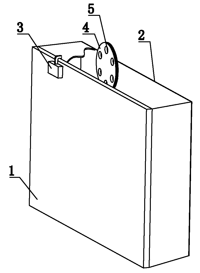
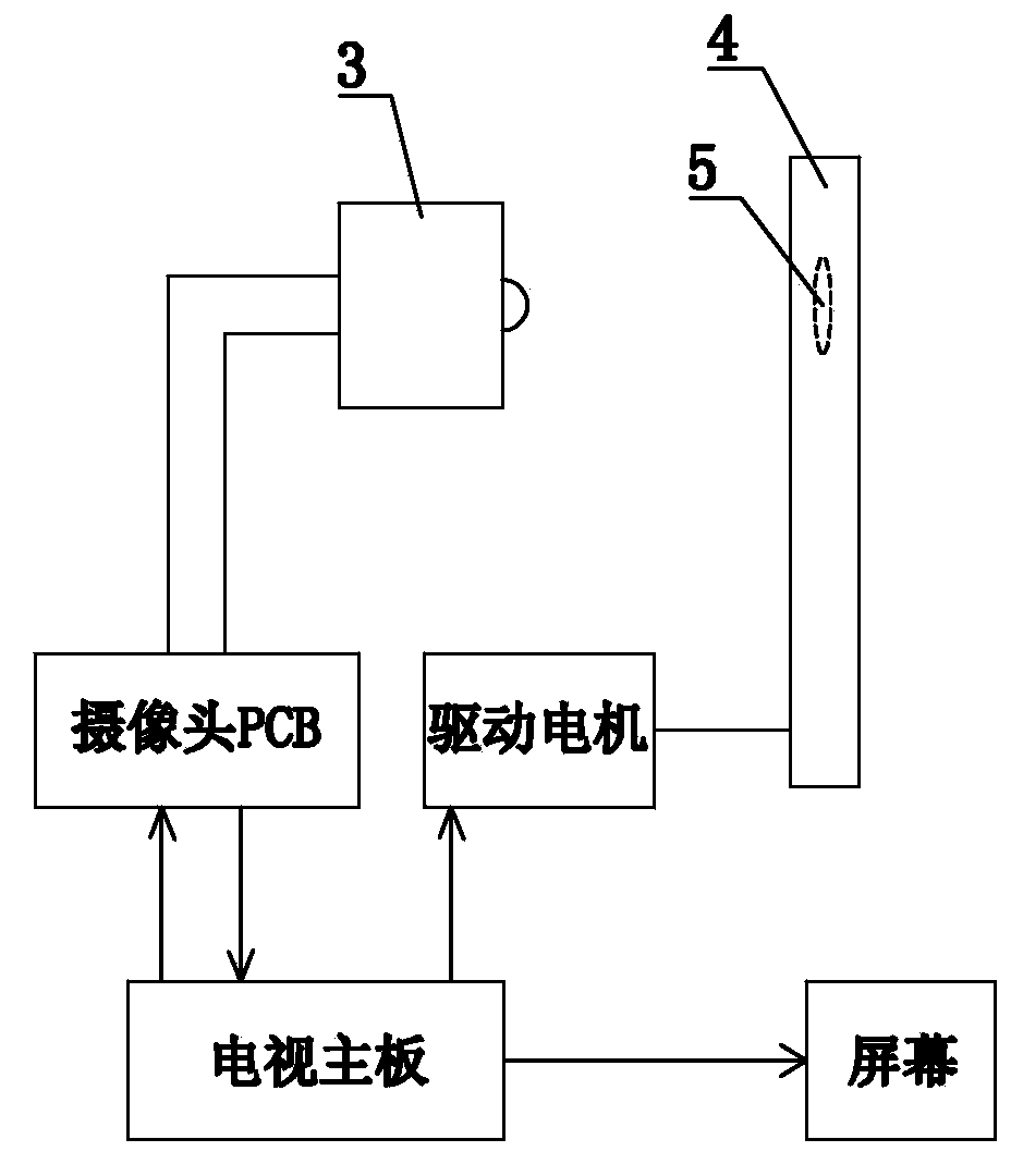
[0033] Such as figure 1 with figure 2 shown ( figure 1 Only the structural features relevant to this application are shown in ), the camera has a smart TV with zoom function, the casing and the screen 2 installed in front of the casing, the upper rear of the casing (ie figure 1 The rear casing 1) shown in the figure is equipped with a camera 3, the lens of the camera 3 protrudes from the top of the casing, and the teleconverter array disk 4 opposite to the camera 3 is installed on the rear side of the screen 2, and the disk surface of the array disk 4 It is circular and parallel to the surface of the screen 2. Several teleconverters 5 with different magnifications are installed on the array disk 4, and one of the teleconverters has a magnification of 1 times, that is, the original scale imaging. The teleconverter 5 on the array disk 4 is in an annular array, and a teleconverter located on the top of the array disk 4 also protrudes from the top of the casing. The lens of the...
Embodiment 2
[0041] Such as Figure 4 As shown, in this embodiment, the disk surface of the teleconverter array disk 4 is cross-shaped, and the teleconverter mirrors 5 on the array disk are in a cross-shaped array.
[0042] The power device for driving the movement of the array disk 4 includes: a horizontal drive motor for driving the array disk to move in the horizontal direction, and a vertical drive motor for driving the array disk to move in the vertical direction. The horizontal drive motor passes through the gear at its output end and The horizontal transmission rod 61 meshed with the gear is in transmission connection with the array disk; the vertical drive motor is in transmission connection with the array disk through the gear at its output end and the vertical transmission rod 62 meshed with the gear.
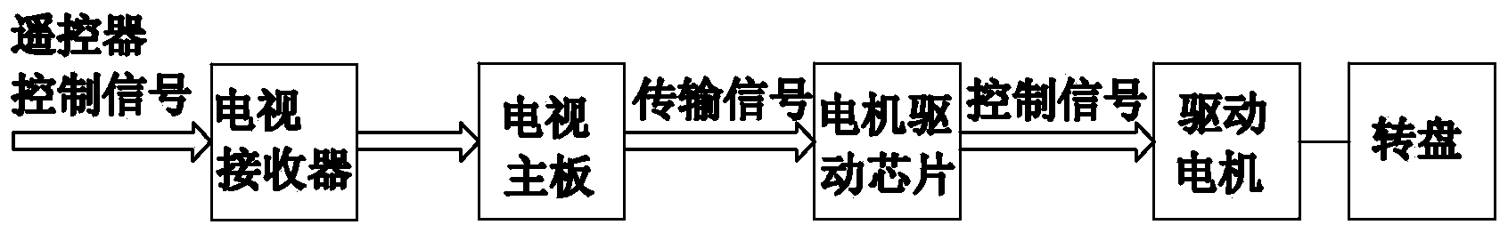
[0043]When the teleconverter 5 is switched, the remote control sends out a control signal. After the TV receives the signal from the remote control, the TV main board transmits th...
Embodiment 3
[0046] In this embodiment, the disk surface of the teleconverter array disk is in the shape of a line, which is equivalent to the horizontal part or the vertical direction part of the cross-shaped array disk, and the teleconverter mirrors are arranged in a straight line along the extending direction of the array disk.
[0047] The power device includes a driving motor for driving the linear movement of the array disk, the driving motor is connected to the array disk through a transmission rod and a gear, and drives the array disk to make a linear reciprocating motion to switch the teleconverter.
[0048] In other embodiments of the present invention, the disk surface of the array disk can also be in other combinations of horizontal and vertical, such as a T or L shape that is placed upright, upside down, left horizontally, or right horizontally. The corresponding T-shaped array and L-shaped array in the placement direction of the distance mirror will not be repeated here.
[0...
PUM
 Abstract
Description
Claims
Application Information
 - R&D
- Intellectual Property
- Life Sciences
- Materials
- Tech Scout
- Unparalleled Data Quality
- Higher Quality Content
- 60% Fewer Hallucinations
Browse by: Latest US Patents, China's latest patents, Technical Efficacy Thesaurus, Application Domain, Technology Topic, Popular Technical Reports.
© 2025 PatSnap. All rights reserved.Legal|Privacy policy|Modern Slavery Act Transparency Statement|Sitemap|About US| Contact US: help@patsnap.com