
Device and method for monitoring and testing seepage speed of porous medium structural body

A technology of porous media and test equipment, applied in the direction of using thermal variables to measure fluid velocity, etc., can solve problems such as missing measurements, large monitoring blind spots, and immature theories

Active Publication Date: 2013-11-27
HOHAI UNIV
View PDF7 Cites 23 Cited by
  • Summary
  • Abstract
  • Description
  • Claims
  • Application Information

AI Technical Summary

Problems solved by technology

[0003] A large amount of engineering experience shows that strengthening the real-time positioning and quantitative monitoring of seepage and seepage deformation of earth-rock dams is of great significance to ensure the safe operation of the project. While the traditional monitoring technology is continuously improved and developed, more and more New technologies have been introduced into the field of dam safety monitoring, and research on the monitoring principles, implementation methods, and technologies of new technologies in the field of dam engineering has become a hot scientific research topic; The spatial discontinuity and missing measurement of the measured value, the distributed and continuous real-time monitoring and measurement of dam leakage by distributed optical fiber temperature sensing technology have attracted great attention from the engineering and academic circles, but the application of this technology in leakage monitoring Theories in this field are still immature, especially the quantitative relationship model between the temperature rise of optical fiber heating and the seepage velocity, ambient temperature, and heating power has not been established. Therefore, it is of great significance to carry out theoretical research and model tests on the seepage velocity monitoring of earth-rock dams.

Method used


Image

  • Device and method for monitoring and testing seepage speed of porous medium structural body
  • Device and method for monitoring and testing seepage speed of porous medium structural body
  • Device and method for monitoring and testing seepage speed of porous medium structural body

Examples


Embodiment 1

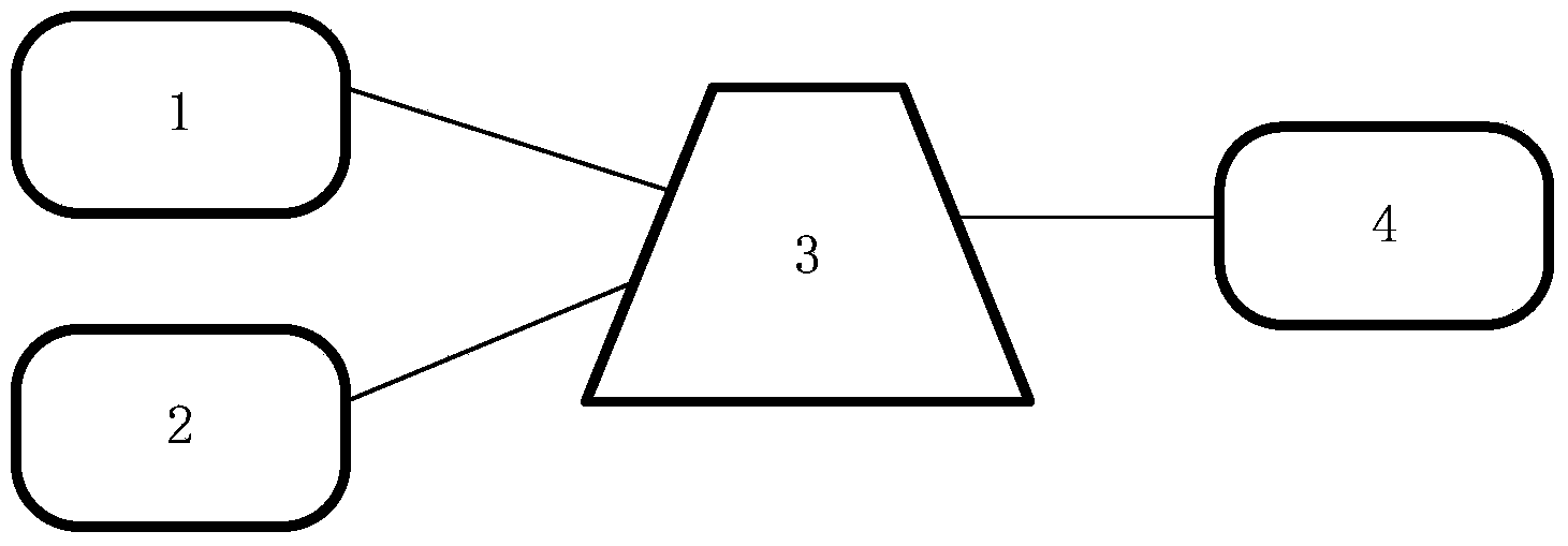
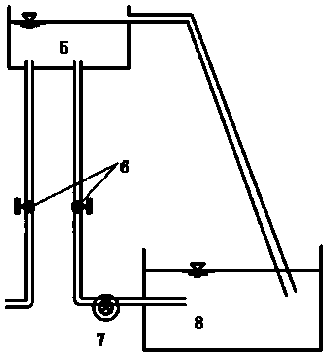
[0055] Embodiment 1: The test device for monitoring seepage velocity of porous media structure according to the present invention, the device schematic diagram is as follows figure 1 As shown, it includes a heating system 1, a distributed optical fiber temperature sensing system 2, a porous medium structure model tank 3 embedded with a monitoring optical fiber, and a water outlet system 4; the heating system 1, the distributed optical fiber temperature sensing system 2 and the water outlet system The system 4 is respectively connected with the porous medium structure model tank 3 .

[0056] The heating system such as Figure 5 As shown, a parallel circuit mainly composed of an AC power supply 9, a voltage regulator 10 and a load heating resistance wire 11 is used to heat the monitoring optical fiber through the load heating resistance wire 11, and the voltage is controlled by the voltage regulator 10 to control the heating power; the distribution The optical fiber temperatur...


PUM


Abstract

The invention discloses a device for monitoring and testing the seepage speed of a porous medium structural body. The device comprises a heating system (1), a distributed optical fiber temperature sensing system (2), a porous medium structural body model slot (3) and a water outlet system (4), wherein a monitoring optical fiber is buried in the porous medium structural body model slot (3), and the heating system (1), the distributed optical fiber temperature sensing system (2) and the water outlet system (4) are connected with the porous medium structural body model slot (3) respectively. The invention further discloses a method for monitoring and testing the seepage speed of the porous medium structural body. The method breaks the mode that in a conventional method for monitoring optical fiber seepage, the motoring period is the heating temperature rise period of the whole optical fiber, the linear dependence of the seepage speed and the average heat conduction coefficient is accurately located, and monitoring accuracy is reliably guaranteed.

Description

technical field [0001] The invention relates to a porous medium structure body seepage flow velocity monitoring test device and method. Background technique [0002] The No. 1 document of the central government on water conservancy construction has accelerated the pace of my country's water conservancy construction. The main problems faced by my country's earth-rock dam projects include leakage, piping, collapse, cracks, landslides, slope protection damage, and erosion cavitation. Seepage is an important factor affecting the safety of dams. If the hidden danger of leakage is not discovered in time and the seepage control measures are not in place, it is very likely to cause seepage damage and dam slope instability, which will seriously affect the safety of the project and even cause the dam to fail. According to statistics, more than one-third of the damage in earth-rock dam projects is caused by various degrees of leakage and various problems derived from leakage; more than...

Claims


Application Information

Patent Timeline
Patent Type & Authority Applications(China)
IPC IPC(8): G01P5/10
Inventor 苏怀智崔书生杨孟欧斌房彬
Owner HOHAI UNIV
Learn More