


Quick Research
Generate reliable direction feasibility study reports for your R&D in just a few steps.

Technical Q&A
Discover and master advanced knowledge NOW. Basics, ideas, possibilities, all at once.

Find Solutions
As an expert in R&D theories, this can generate solutions to your technical problems instantly.

Evaluate Feasibility
Analyze your overall solution with one click, know your potential R&D risks in advance.

Monitor Landscape
Get weekly tech updates, stay abreast of the latest tech innovations and key insights.
Vaporized petroleum gas blast burner
A burner, petroleum gas technology, applied in the direction of gas fuel burners, burners, combustion methods, etc., can solve the problems of personal safety hazards of workers, casualties and property, difficult flame control, etc., and achieve good energy saving effect and sufficient combustion. Quick, easy to install and operate
- Summary
- Abstract
- Description
- Claims
- Application Information
AI Technical Summary
Problems solved by technology
Method used
Image

Examples
Embodiment 1
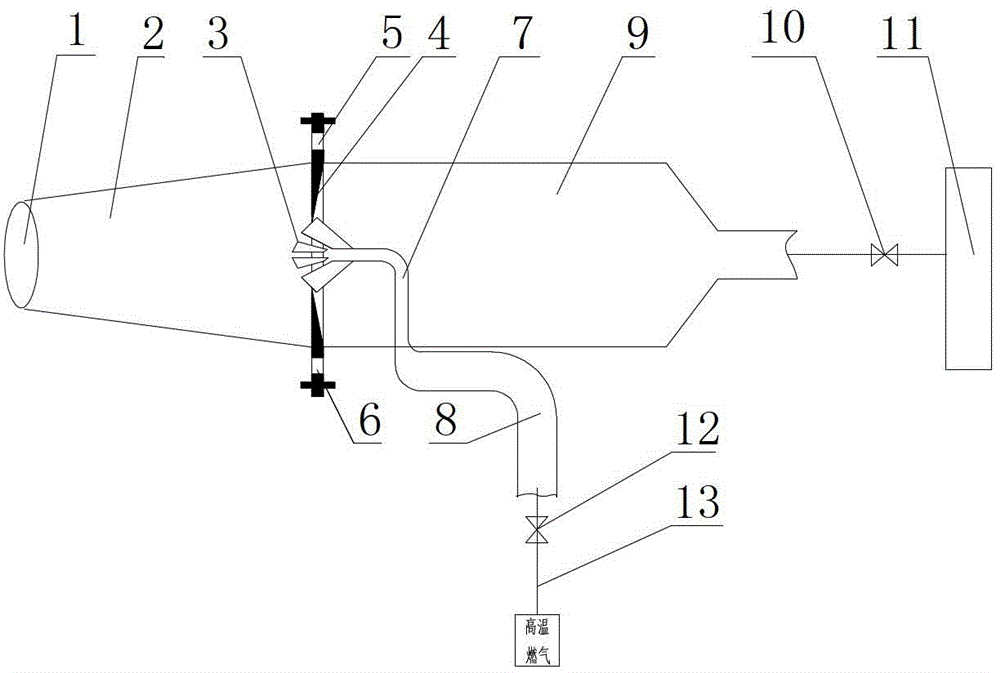
[0025] The vaporized petroleum gas blast burner of the present embodiment has a structure such as figure 1 Shown, comprise air duct 9, the inlet of air duct 9 is connected with the compression fan 11 that is connected with damper 10, and the outlet is connected with air-wind mixing pipe 2, and the end of air-air mixing pipe 2 is provided with flame outlet 1, and air duct 9 The upper end of the outlet is provided with a fire viewing hole 5, and the lower end is provided with an ignition port 6. An air disc 4 is embedded at the junction of the outlet of the air duct 9 and the air-wind mixing pipe 2. The middle part of the air disc 4 is equipped with a nozzle 3, and the nozzle 3 passes through the conduit and The air supply pipe 13 connected with the air supply valve 12 is connected. Among them, the conduit is composed of a thin conduit 7 (copper pipe) arranged inside the air duct 9 and connected to the nozzle 3, and a thick conduit 8 arranged outside the air duct 9 and connected...
Embodiment 2
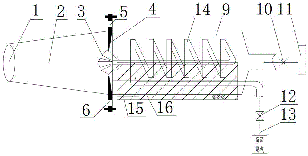
[0029] The vaporized petroleum gas blast burner of the present embodiment has a structure such as figure 2Shown, comprise air duct 9, the inlet of air duct 9 is connected with the compression fan 11 that is connected with damper 10, and the outlet is connected with air-wind mixing pipe 2, and the end of air-air mixing pipe 2 is provided with flame outlet 1, and air duct 9 The upper end of the outlet is provided with a fire viewing hole 5, and the lower end is provided with an ignition port 6. An air disc 4 is embedded at the junction of the outlet of the air duct 9 and the air-wind mixing pipe 2. The middle part of the air disc 4 is equipped with a nozzle 3, and the nozzle 3 passes through the conduit and The air supply pipe 13 connected with the air supply valve 12 is connected. Among them, the conduit is a spiral pipe 14 spirally wound inside the air duct, with the same pipe diameter, the expansion distance between two adjacent spiral pipes and the distance between the spir...
Embodiment 3
[0032] The difference between this embodiment and the second embodiment is that the conduit is composed of a thin conduit arranged inside the air duct 9 and connected to the nozzle 3 and a thick conduit arranged outside the air duct 9 and connected to the air supply pipe 13, wherein the thin conduit It is a helical duct 14 spirally coiled inside the air duct 9, the expansion distance between two adjacent helical ducts and the distance between the helical duct and the duct wall are 5-10mm, and there is a slope of 180° between the helical duct 14 and the thick duct. The inner diameter of the thick conduit is 37.5 mm, the inner diameter of the spiral pipe 14 is 4 mm, and the combustion efficiency can reach 31.4%. The results are shown in Table 1. There is an angle of 40° between the rotating wind ejected from the rotating wind disk and the nozzle, so as to form a negative pressure and form a negative pressure zone in front of the nozzle. The taper of the air-wind mixing pipe 2 is...
PUM
 Abstract
Description
Claims
Application Information
 - R&D Engineer
- R&D Manager
- IP Professional
- Industry Leading Data Capabilities
- Powerful AI technology
- Patent DNA Extraction
Browse by: Latest US Patents, China's latest patents, Technical Efficacy Thesaurus, Application Domain, Technology Topic, Popular Technical Reports.
© 2024 PatSnap. All rights reserved.Legal|Privacy policy|Modern Slavery Act Transparency Statement|Sitemap|About US| Contact US: help@patsnap.com