


Quick Research
Generate reliable direction feasibility study reports for your R&D in just a few steps.

Technical Q&A
Discover and master advanced knowledge NOW. Basics, ideas, possibilities, all at once.

Find Solutions
As an expert in R&D theories, this can generate solutions to your technical problems instantly.

Evaluate Feasibility
Analyze your overall solution with one click, know your potential R&D risks in advance.

Monitor Landscape
Get weekly tech updates, stay abreast of the latest tech innovations and key insights.
Expansion capsule providing power and power drive device
A power-driven, capsule technology, applied in the direction of mechanisms, machines/engines, and mechanical equipment that generate mechanical power, can solve problems such as slow ejection and recovery speeds of the ejector rod and piston, damage to seals 3, and long expansion distances.
- Summary
- Abstract
- Description
- Claims
- Application Information
AI Technical Summary
Problems solved by technology
Method used
Image

Examples
Embodiment 1
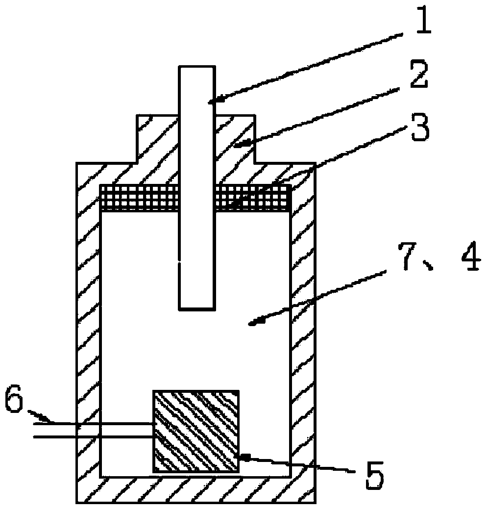
[0059] Figure 2-4 It is a structural schematic diagram of the first embodiment of the present invention. in, figure 2 It is a perspective view of the expanding capsule in the first embodiment of the present invention. image 3 It is a sectional view of the expanding capsule in the first embodiment of the present invention. Figure 4It is a sectional view of the power drive device in the first embodiment of the present invention.
[0060] Such as image 3 As shown, the powered expansion capsule 100 includes a heating element 10 and an expansion medium 20 , the expansion medium 20 evenly wraps the heating element 10 , and together constitute an expansion assembly, the expansion assembly is wrapped with a layer of elastic member 30 . In this embodiment, the expansion capsule 100 is in the shape of a ring column, and the heating element 10 is a resistance wire. The resistance wire can be wound into multiple turns and then folded up and down and directly stored in the elastic...
Embodiment 2
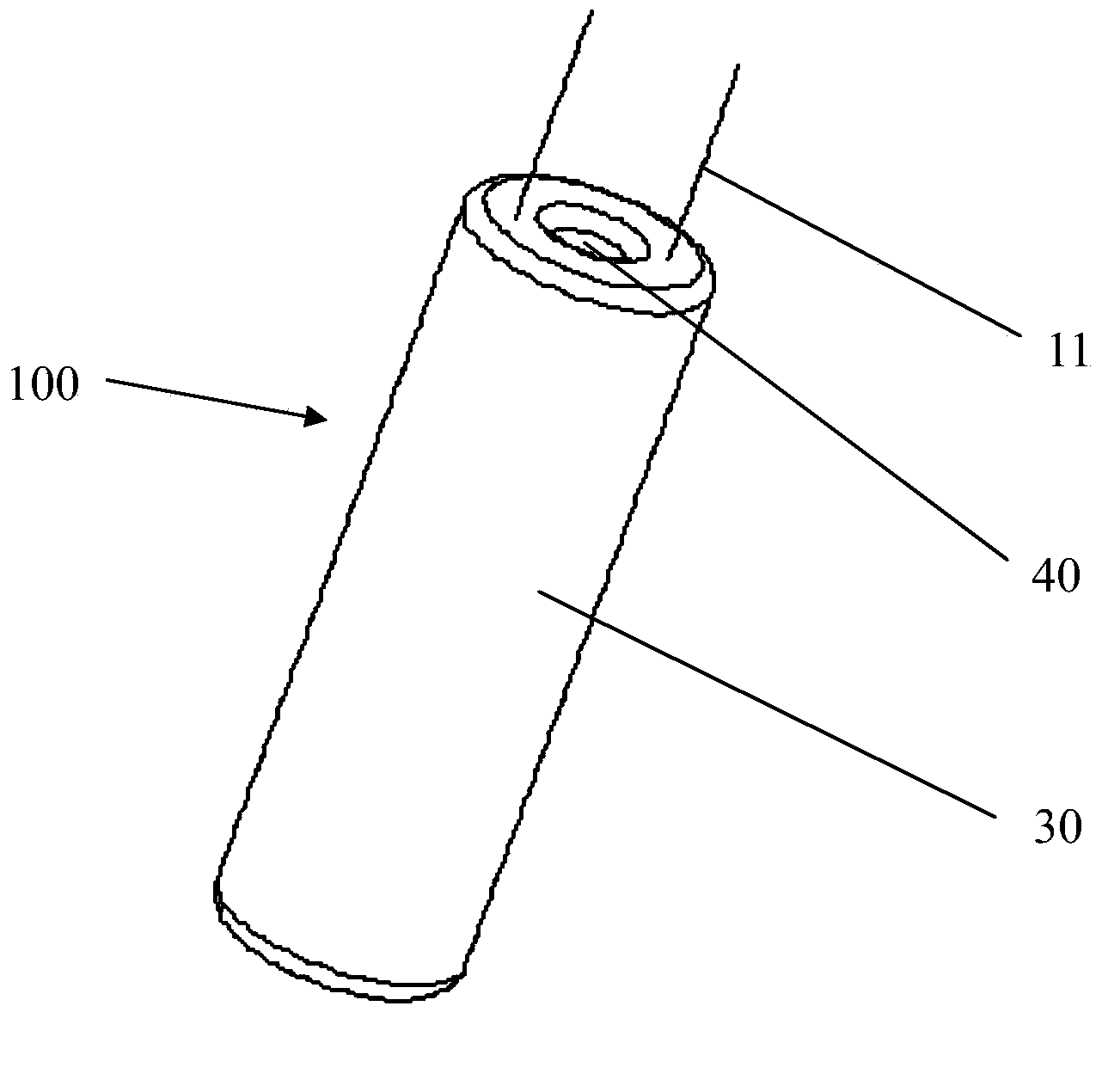
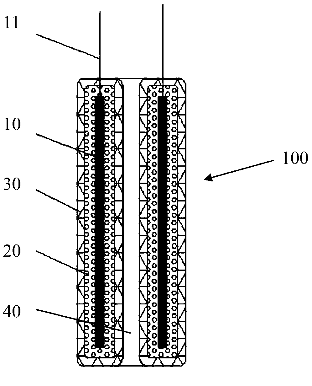
[0075] Figure 6-8 It is a structural schematic diagram of the second embodiment of the present invention. in, Figure 6 It is a perspective view of the expanding capsule in the second embodiment of the present invention. Figure 7 It is a sectional view of the expanding capsule in the second embodiment of the present invention. Figure 8 It is a sectional view of the power drive device in the second embodiment of the present invention.
[0076] The difference between this embodiment and the first embodiment is that the expansion capsule is cylindrical, the elastic member 30 is a cylindrical hollow closed capsule, and the heating element 10 and the expansion medium 20 are accommodated in the elastic member 30 . Two wires 11 are drawn out from the heating element 10, and the expansion medium 20 and the elastic member 30 are sequentially wrapped on the outer surface of the heating element 10 to form a cylindrical expansion capsule. The bottom end of the piston rod 60 is loca...
Embodiment 3
[0082] Figure 10-12 It is a structural schematic diagram of the third embodiment of the present invention. in, Figure 10 It is a perspective view of the expansion assembly and the elastic member in the expansion capsule in the third embodiment of the present invention, Figure 11 It is a perspective view of the rigid shell in the expandable capsule in the third embodiment of the present invention, Figure 12 It is a sectional view of the power drive device in the third embodiment of the present invention.
[0083] The difference between this embodiment and the first embodiment is that the expansion capsule is in the shape of a ring column, the heating element 10 is a resistance wire, the resistance wire can be wound into multiple turns, and the heating element 10 is heated after being energized through the wire 11; the outer surface of the heating element 10 The expansion medium 20 is completely and evenly wrapped to form the expansion assembly 12 together; the elastic me...
PUM
 Abstract
Description
Claims
Application Information
 - R&D Engineer
- R&D Manager
- IP Professional
- Industry Leading Data Capabilities
- Powerful AI technology
- Patent DNA Extraction
Browse by: Latest US Patents, China's latest patents, Technical Efficacy Thesaurus, Application Domain, Technology Topic, Popular Technical Reports.
© 2024 PatSnap. All rights reserved.Legal|Privacy policy|Modern Slavery Act Transparency Statement|Sitemap|About US| Contact US: help@patsnap.com