Eureka AIR delivers breakthrough ideas for toughest innovation challenges, trusted by R&D personnel around the world.

A floating valve type spray bag for amorphous tape

A technology for making an amorphous tape and a floating valve, which is applied in the field of the floating valve type spray bag for the amorphous tape, can solve the problems of difficulty in stably controlling the liquid level of the spray bag, waste of raw materials, and inconvenient loading and unloading.

Active Publication Date: 2015-11-18
ANHUI HUAJING MACHINERY
View PDF7 Cites 0 Cited by
  • Summary
  • Abstract
  • Description
  • Claims
  • Application Information

AI Technical Summary

Problems solved by technology

At this time, because the molten iron in the spray ladle is extremely unstable, there is a lot of scum, and the pressure is not enough, when the ladle is filled with molten iron, it takes several seconds to gradually stabilize, and the strip before stabilization cannot meet the use requirements
At the same time, it is difficult to control the liquid level of the spray ladle stably when pouring manually, and the automatic liquid level control system is complicated and costly
[0003] In the existing spraying process, the molten iron in the spraying ladle cannot actively stop pouring. During the continuous spraying process, the surface of the nozzle and the cooling roller is severely deformed by the high-temperature molten iron, which reduces the quality of the strip and the service life of the equipment.
At the same time, when the spraying belt is abnormally interrupted in the existing design of the spraying ladle, the high-temperature molten iron in the ladle still needs to flow by itself, which causes safety hazards to equipment and operators while wasting raw materials, and is inconvenient for loading and unloading

Method used


Image

  • A floating valve type spray bag for amorphous tape
  • A floating valve type spray bag for amorphous tape

Examples


Embodiment Construction

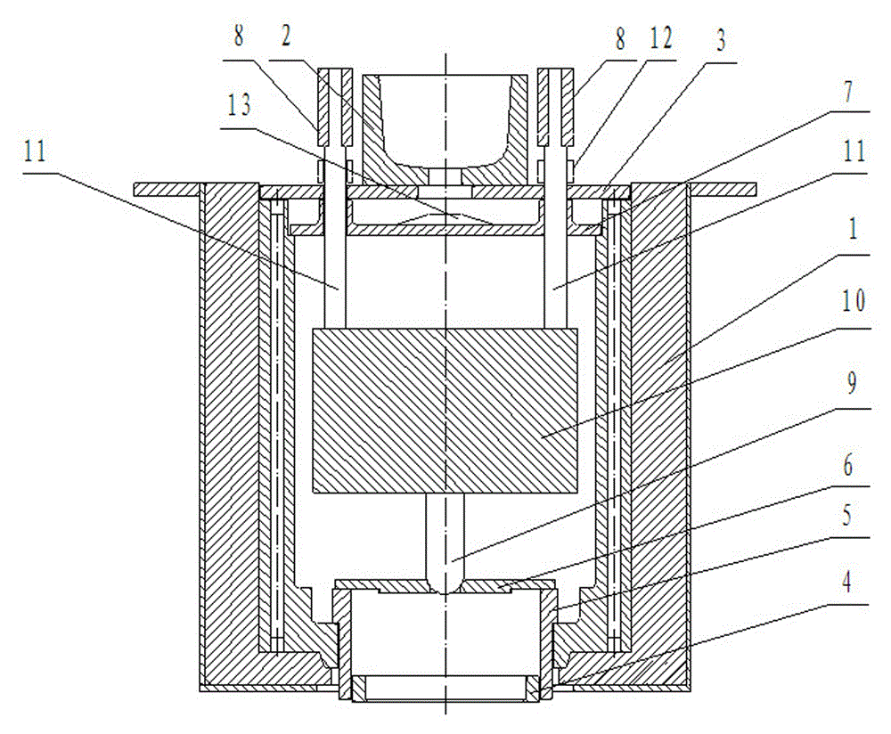
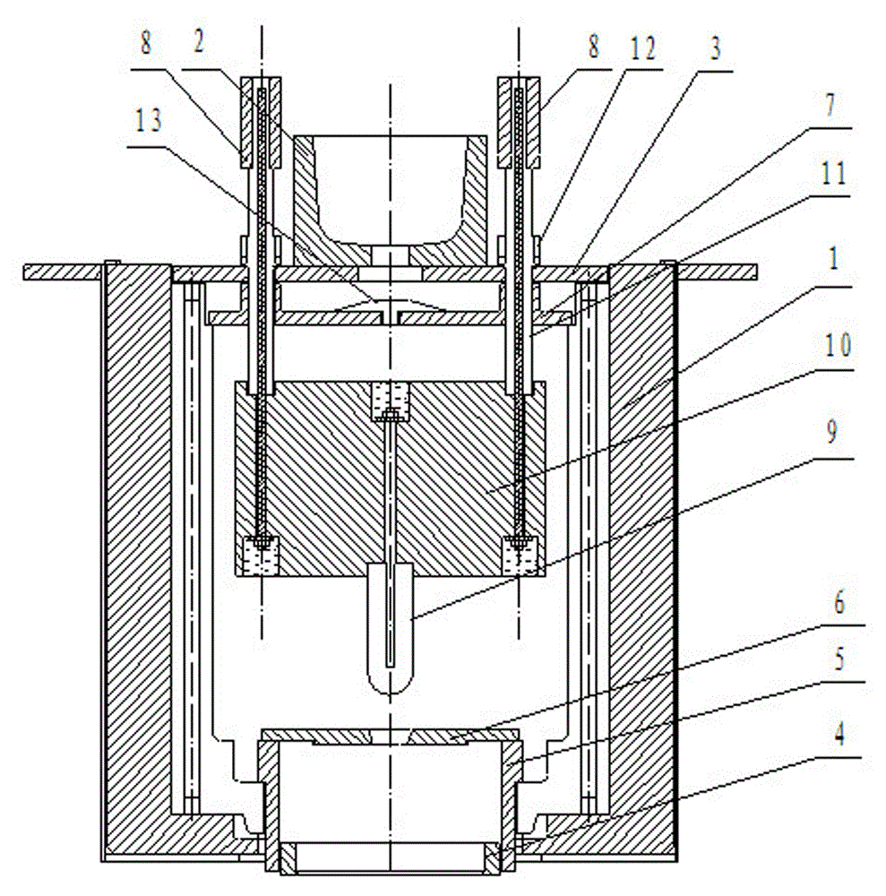
[0010] A float-valve spray bag for amorphous tape making according to the present invention will be described in further detail below in conjunction with the accompanying drawings.

[0011] Depend on figure 1 , As can be seen from the figure, a kind of floating valve type spray bag for amorphous tape in this embodiment is composed of spray bag 1, water inlet 2, water outlet seat plate 3, nozzle 4 and nozzle seat 5, valve stem seat 6, and float valve device , a baffle plate 7, two left and right counterweights 8, the water outlet seat plate 3 is fixed on the upper end of the spray bag 1, the water outlet seat plate 3 is fixed with a water inlet 2, and the bottom of the spray bag 1 is provided with a nozzle Seat 5, the lower end of nozzle seat 5 is provided with nozzle 4, is fixedly provided with valve stem seat 6 on nozzle seat 5. The floating valve device is located in the cavity of the spray bag 1, and is composed of a valve stem 9, a floating block 10 and two guide rods 11 ...


PUM


Abstract

The invention discloses a float valve type spraying pack for preparing amorphous strip. The float valve type spraying pack for preparing the amorphous strip comprises a spraying pack body, a molten iron taking port, a molten iron taking port base board, a spraying nozzle, a nozzle seat, a valve rod seat, a float valve unit, a baffle, a left counter weight and a right counter weight. The float valve unit is arranged inside the cavity of the spraying pack body and is composed of a valve rod, a float block, a left guide rod and a right guide rod, and the lower end of the valve rod is connected with a central hole of the valve rod seat in a centering joint mode; the top end of each guide rod is provided with the corresponding counter weight; the baffle is movably arranged inside a groove at the upper end of the spraying pack body and provided with a molten iron separation cone. According to the technical scheme, the float valve type spraying pack for preparing the amorphous strip can control the molten iron level freely, achieve strip spraying at intervals actively and stop automatic molten iron discharge when abnormal strip spraying occurs and meanwhile is simple in structure, low in cost, safe, reliable and capable of prolonging the service life of equipment.

Description

technical field [0001] The invention belongs to the field of metal material preparation, and is particularly suitable for a float-valve type spray bag for making amorphous tapes. Background technique [0002] In the prior art, rapid solidification technology is usually used for the preparation of amorphous alloy thin strips, and molten iron is poured onto the surface of rotating cooling rolls through spray ladles equipped with nozzles to form thin strips. Among them, the gravity belt-making equipment relies on the self-weight pouring of molten iron in the spray ladle. When the spray ladle starts to inject molten iron, the spray belt has already started. At this time, because the molten iron in the spray ladle is extremely unstable, there is a lot of scum, and the pressure is not enough, when the ladle is filled with molten iron, it takes several seconds to gradually stabilize, and the strip before stabilization cannot meet the use requirements. At the same time, it is diffi...

Claims


Application Information

Patent Timeline
IPC IPC(8): B22D11/10B22D11/06
Inventor 王刚朱乐琦
Owner ANHUI HUAJING MACHINERY
Why Eureka
Eureka Blog
Learn More