
Method for determining a property of a fuel

A fuel and performance technology, applied in the direction of fuel injection device, fuel injection control, charging system, etc., can solve the problems of insufficient correction, correction, etc., and achieve the effect of reducing the amount error

Active Publication Date: 2013-11-20
ROBERT BOSCH GMBH
View PDF9 Cites 2 Cited by
  • Summary
  • Abstract
  • Description
  • Claims
  • Application Information

AI Technical Summary

Problems solved by technology

As long as there is no possibility in the CRS to determine important fuel properties, for example by means of sensors, the correction of the quantitative influence of these properties is insufficient or not possible at all

Method used


Image

  • Method for determining a property of a fuel
  • Method for determining a property of a fuel
  • Method for determining a property of a fuel

Examples


Embodiment Construction

[0027] The invention is schematically illustrated in the drawings with the aid of embodiments and is described below with reference to the drawings. It should be noted that the numerical values ​​and numerical ranges mentioned in the drawings and the description are indicated by way of example only.

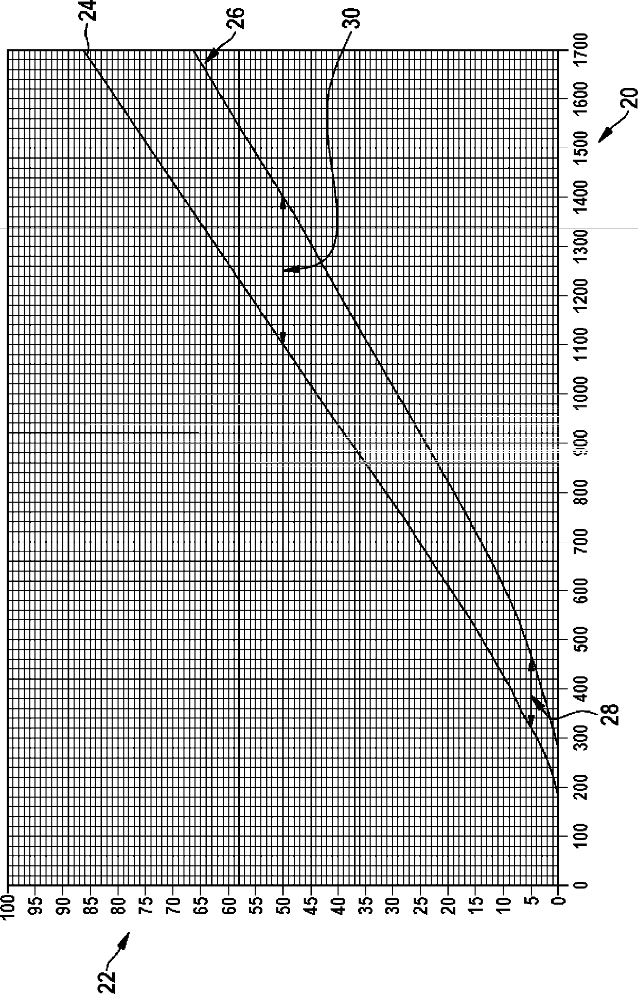
[0028] exist figure 1 In the graph of , the actuation duration in μs is plotted along the abscissa 20 and the duration in mm is plotted along the ordinate 22 3 The gauge used for fuel injection. exist figure 1 A first curve 24 and a second curve 26 for a so-called winter diesel are shown in the diagram of the injection quantity as a function of the control duration for a so-called arctic diesel which is generally suitable for low temperatures.

[0029] The difference in the actuation duration as a dynamic characteristic of an injection valve, for example a solenoid valve, is shown by the two double arrows 28 , 30 at a constant injection quantity for the two fuel types. Ther...


PUM


Abstract

The invention relates to a method for determining at least one property of a fuel, in which method a closed period of an armature of a solenoid valve, which moves through the fuel, is measured in at least one triggering period, and a factor is determined on the basis of the measured closed period, which factor represents the at least one property of the fuel.

Description

technical field [0001] The invention relates to a method for determining at least one property of a fuel, a method for operating an internal combustion engine, and a device for carrying out the method. Background technique [0002] In the case of a common rail system (CRS), the injection quantities depend, inter alia, on various fuel properties, which in turn depend on the type of fuel and the ambient conditions. For example, the viscosity of fuel grades such as winter diesel, arctic diesel, biodiesel, mixtures of different fuel grades also additionally depends on the temperature. As long as there is no possibility in the CRS to determine relevant fuel properties, for example by means of sensors, the correction of the quantitative influence of these properties is insufficient or not possible at all. [0003] It should be noted that a longer start time is generally permitted for a cold start to be performed below freezing than for a start above freezing. The requirements re...

Claims


Application Information

Patent Timeline
Patent Type & Authority Applications(China)
IPC IPC(8): F02D41/40F02M65/00
CPCY02T10/44F02D19/0636F02M65/005F02D41/401F02D2200/0612F02D2200/063Y02T10/30Y02T10/40F02D41/40F02M65/00G01N33/28
Inventor M.西登托普夫S.施平德勒M.霍恩A.雷蒂希F.霍夫曼
Owner ROBERT BOSCH GMBH
Learn More