
Automation-technology-based generating set dehumidification device and operating method for same

An automation technology and technology of generator sets, which are applied in the direction of using electric means for temperature control, auxiliary controllers with auxiliary heating devices, etc. The effect of reducing energy consumption, rational heating process and cost reduction

Active Publication Date: 2013-11-20
NINGBO C S I POWER & MASCH GRP CO LTD
View PDF5 Cites 2 Cited by
  • Summary
  • Abstract
  • Description
  • Claims
  • Application Information

AI Technical Summary

Problems solved by technology

However, when used in tropical, subtropical climates, coastal areas and islands, when the generator set is in a stopped state, when the ambient temperature is higher than the temperature of the generator winding, water droplets are easy to condense on the generator winding, and these water droplets will make the generator winding Moisture will affect the normal operation of the generator set, so it is necessary to install a dehumidification device on the generator winding
The existing dehumidification device uses a low-power heater to heat the winding and end iron core of the generator, thereby protecting the insulation of the generator winding. The dehumidification device needs to be controlled for heating. After the switch is turned on It will work continuously, although the power of the heater is not large, but in the state of continuous heating, it consumes a lot of electric energy, which causes a lot of waste of electric energy

Method used


Image

  • Automation-technology-based generating set dehumidification device and operating method for same
  • Automation-technology-based generating set dehumidification device and operating method for same
  • Automation-technology-based generating set dehumidification device and operating method for same

Examples


Embodiment Construction

[0028] The present invention will be further described in detail below in conjunction with the accompanying drawings and embodiments.

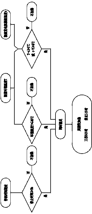
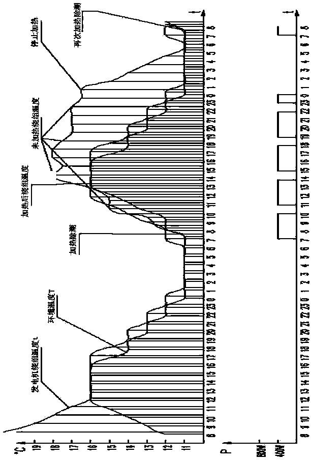
[0029] Such as Figure 1 to Figure 2 Shown is the structural representation of the present invention, image 3 is the application experiment curve of the present invention,

[0030] The reference signs therein are:

[0031] Such as Figure 1 to Figure 2 As shown, ambient temperature T, generator winding temperature t, heater 1, controller 2, ambient temperature monitor 3, generator temperature monitor 4, delay timer 5, temperature comparator 6, logic controller 7.

[0032] A kind of dehumidification device of a generator set based on automation technology of the present invention includes a heater 1, a controller 2, and an ambient temperature monitor 3 installed outside the generator set for real-time measurement of the ambient temperature T of the generator installation location, A generator temperature monitor 4 installed in the generato...


PUM


Abstract

The invention discloses an automation-technology-based generating set dehumidification device, which comprises a heater, a controller, an environmental temperature monitor, a generator temperature monitor, a delay timer, a temperature comparator and a logic controller, wherein the environmental temperature monitor is arranged outside a generating set, and is used for measuring the environmental temperature of a generator mounting position in real time; the generator temperature monitor is arranged in the generating set, and is used for measuring the temperature of a generator winding in real time; the temperature comparator is connected and matched with the environmental temperature monitor; the logic controller is connected and matched with the environmental temperature monitor and the generator temperature monitor respectively; and the controller is in signal connection with the delay timer, the temperature comparator and the logic controller, and is used for starting and stopping the heater according to a judgment result. According to the device, an automation technology is utilized, the environmental temperature and the temperature of the generator winding are monitored in real time, and the controller makes a judgment, and controls the heater to perform dehumidification and heating, so that a heating process is reasonable, the aim of dehumidification is fulfilled, electric energy is saved, and cost is lowered.

Description

technical field [0001] The invention relates to the technical field of generating sets, in particular to an automation-based dehumidification device for generating sets and an operating method thereof. Background technique [0002] Automation technology is a comprehensive technology, which has a very close relationship with cybernetics, information theory, system engineering, computer technology, electronics, hydraulic and pneumatic technology, and automatic control. With the continuous development of science and technology, automation technology has been applied and developed in various fields. The application of automation technology has changed production from manual operation to mechanized operation, and equipment control has changed from manual control to intelligent control. The degree of automation has been continuously strengthened, production efficiency has been continuously improved, and labor costs have been continuously reduced. [0003] Due to its easy installa...

Claims


Application Information

Patent Timeline
Patent Type & Authority Applications(China)
IPC IPC(8): G05D23/30
Inventor 林坚树吴杰
Owner NINGBO C S I POWER & MASCH GRP CO LTD
Learn More