A device and method for synchronous trigger management
A technology for synchronous triggering and management devices, applied in the direction of instruments, computer control, simulators, etc., can solve the problems of difficult management and unification of distributed test system triggers, inability of instruments to synchronize and trigger, and difficulty in building distributed test systems
- Summary
- Abstract
- Description
- Claims
- Application Information
AI Technical Summary
Problems solved by technology
Method used
Image
Examples
Embodiment
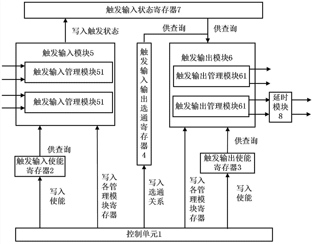
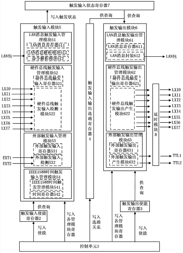
[0062] figure 2 It is a schematic structural diagram of an embodiment of a synchronization trigger management device in the present invention. Such as figure 2 As shown, the trigger input module 5 in this embodiment includes four common trigger input management modules in the prior art, which are respectively a LAN message trigger input management module 51, an 8-channel hardware bus trigger input management module 52, and a two-channel trigger input management module. An external trigger input management module 53 and an IEEE1588 time trigger input management module 54 . The trigger output module 6 includes three trigger output management modules, namely, a LAN message trigger output management module 61 , a hardware bus trigger output management module 62 , and an external trigger output management module 63 . The trigger input management module and the trigger output management module are not limited to those listed, and in implementation applications, one of the trigge...
application example 1
[0157] Figure 11 is a schematic diagram of Application Example 1 of the present invention. Such as Figure 11 As shown, the oscilloscope is an instrument that does not have a LAN port (network port) and cannot be connected to a local area network. It only has an external trigger input port EXT, and cannot directly control the trigger acquisition action of the oscilloscope through the local area network. The LAN port of the computer is directly connected to the LAN port of the synchronous trigger management device through a network cable, and the external trigger output port TTL1 of the synchronous trigger management device is directly connected to the external trigger input port EXT of the oscilloscope through a coaxial cable. Set the trigger input mode of the synchronous trigger management device to be LAN trigger, and the trigger output mode to be external trigger output, and output from external trigger output port 1 (TTL1 port). At this time, the computer sends LAN data...
application example 2
[0160] Figure 12 is a schematic diagram of application example 2 of the present invention. Such as Figure 12 As shown, the signal source has an external trigger function, but does not have the LXI hardware bus trigger function. Sources, computers, hubs, sync trigger managers, and LXI Class A oscilloscopes are Figure 12 Connected, the external trigger input port 1 (EXT1) of the synchronous trigger management device and the external trigger output port TTL of the signal source are connected through a coaxial cable, and the synchronous trigger management device and the hardware bus trigger interface LXI TRIG of the LXI Class A oscilloscope are connected through the LXI The trigger cable is connected, and the signal output port of the signal source is connected with the signal input channel 1 (CH1) of the LXI Class A oscilloscope through a coaxial cable. Set the trigger output mode of the synchronous trigger management device as hardware bus trigger output, the output channe...
PUM
 Abstract
Description
Claims
Application Information
 - R&D
- Intellectual Property
- Life Sciences
- Materials
- Tech Scout
- Unparalleled Data Quality
- Higher Quality Content
- 60% Fewer Hallucinations
Browse by: Latest US Patents, China's latest patents, Technical Efficacy Thesaurus, Application Domain, Technology Topic, Popular Technical Reports.
© 2025 PatSnap. All rights reserved.Legal|Privacy policy|Modern Slavery Act Transparency Statement|Sitemap|About US| Contact US: help@patsnap.com


