
Indoor pull-out test apparatus for anchor rod

A technology of pull-out test and anchor rod, which is applied in the direction of applying stable tension/pressure to test the strength of materials, etc., can solve the problems of anchorage system failure, simple structure, and lower pull-out force, and achieve wide application range, reasonable design, Easy to install and use

Inactive Publication Date: 2015-04-29
INST OF ROCK & SOIL MECHANICS CHINESE ACAD OF SCI
View PDF11 Cites 0 Cited by
  • Summary
  • Abstract
  • Description
  • Claims
  • Application Information

AI Technical Summary

Problems solved by technology

[0004] (1) Different from the bonded anchor, the main failure mode of the expansion shell anchor in the pull-out test is: as the pull-out force increases, the expansion shell of the anchor expands and cracks the borehole wall , leading to a rapid decrease in the pull-out force
Whether the borehole bursts or not is closely related to the stress state of the sample. However, the traditional indoor pull-out test device for anchor rods has a simple structure and cannot perform pull-out tests under sample loading conditions, so it is not suitable for expanding shells. Indoor Pull-out Test of Type Anchor
[0005] (2) As mentioned in (1), the damage and destruction of the sample is the main reason for the failure of the anchorage system. In the pull-out test of the expansion shell anchor, the damage and damage degree of the sample, The initiation, expansion and penetration of cracks in the sample are very important for the understanding of the anchoring characteristics of the expansion shell anchor and the accurate acquisition of anchoring parameters, but the traditional indoor pull-out test device for anchors cannot meet the above requirements

Method used


Image

  • Indoor pull-out test apparatus for anchor rod
  • Indoor pull-out test apparatus for anchor rod
  • Indoor pull-out test apparatus for anchor rod

Examples


Embodiment Construction

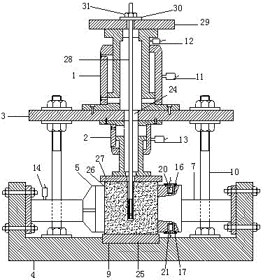
[0014] A bolt indoor pull-out test device of the present invention will be described in further detail below in conjunction with the accompanying drawings.

[0015] see Attachment.

[0016] An indoor pullout test device for anchor rods, the test device is composed of a horizontal loading system, a vertical loading system, an anchor rod pulling system, a box body 4, a support column 10, and a supporting plate 3, and the box body 4 is in an open shape. The horizontal loading system is composed of a first horizontal loading jack 5, a second horizontal loading jack 6, a first horizontal load reaction device 7, and a second horizontal load reaction device 8. The first horizontal loading jack 5 and the second horizontal loading jack 6 They are respectively fixedly arranged on the two inner side walls of the box body 4, the axes of the first horizontal loading jack 5 and the second horizontal loading jack 6 are perpendicular to each other, and the first horizontal load reaction devic...


PUM


Abstract

The invention relates to an indoor pull-out test apparatus for an anchor rod, which belongs to the technical field of geotechnical engineering. The apparatus comprises a horizontal loading system, a vertical loading system, an anchor rod pulling system, a box, support columns and a bearing plate. The test apparatus can realize loading of a sample at two horizontal directions and a vertical direction and overcomes the problem that a traditional indoor pull-out test apparatus for an anchor rod cannot carry out pull-out test under loading conditions; the test apparatus is provided with an acoustic emission sensor, can realize whole-course monitoring of damage, breakage and generation and expansion of cracks in the sample during pull-out test of the anchor rod and overcomes the limitation that mechanical response of an anchoring body cannot be conveniently monitored in traditional indoor pull-out test. The test apparatus provided by the invention can be applied in pull-out experimental study of mechanical behaviors of an expansion shell anchor rod and a corresponding anchoring body in geotechnical engineering so as to provide scientific experimental bases for test of anchoring performance of the expansion shell anchor rod and can also be applied in pull-out experimental study of a bond-type anchor rod.

Description

technical field [0001] The invention relates to an indoor pull-out test device for anchor rods, which belongs to the technical field of geotechnical engineering. The device is mainly used in the indoor pull-out test research of shell-expanding anchor rods in geotechnical engineering. Background technique [0002] Bolt support is an economical and efficient surrounding rock reinforcement method commonly used in geotechnical engineering such as slopes, tunnels, and underground stopes. According to the different anchoring types between the rod body and the rock and soil mass, the common anchor rods can be divided into bonded anchor rods and mechanical anchor rods. Adhesive bolt, the anchoring section uses cement mortar or chemical anchoring agent (such as resin medicine roll, rapid hardening cement, etc.) to tightly bond the rod body and the surrounding rock and soil together, relying on the rod body and the adhesive, bonding The bonding force between the agent and the rock-so...

Claims


Application Information

Patent Timeline
Patent Type & Authority Patents(China)
IPC IPC(8): G01N3/10
Inventor 周辉徐荣超张传庆胡善超卢景景付亚平刘海涛梁恒
Owner INST OF ROCK & SOIL MECHANICS CHINESE ACAD OF SCI
Learn More