Supercharge Your Innovation With Domain-Expert AI Agents!

Blowing draining device for filtering machine

A blowing device, filter technology, applied in the direction of filtration separation, mobile filter element filter, separation method, etc., can solve the problems of poor effect and unsatisfactory filtration effect, achieve low cost, improve solid-liquid separation effect, structure simple effect

Active Publication Date: 2013-11-20
浙江旺能生态科技有限公司
View PDF8 Cites 2 Cited by
  • Summary
  • Abstract
  • Description
  • Claims
  • Application Information

AI Technical Summary

Problems solved by technology

[0003] However, in the actual working process of the existing vacuum belt filter, we found that its filtering effect is still not ideal, especially for viscous materials, the effect of solid-liquid separation is even worse

Method used


Image

  • Blowing draining device for filtering machine
  • Blowing draining device for filtering machine
  • Blowing draining device for filtering machine

Examples


Embodiment 1

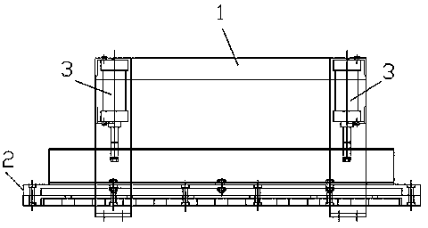
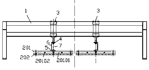
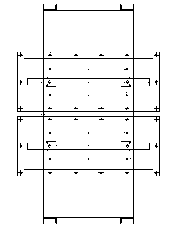
[0034] Embodiment 1, see attached figure 1 , 2 , 3, 4, the air-blowing and drying device used for the filter, including a support 1, an air-blowing device 2 and a lifting mechanism 3 for driving the air-blowing device 2 to lift, and the air-blowing device arranged on the support 1 is based on actual conditions. Determination of demand, in this embodiment, there are two, each air blowing device 2 is brought up and down by a lifting mechanism 3, and the lifting structure 3 is a cylinder or an oil cylinder, in this embodiment, it is two cylinders, and the blowing device 2 The device 2 includes an upper grid plate 201, a lower grid plate 202 fixedly connected with the upper grid plate 201 and a filter cloth 203 fixed on the lower surface of the lower grid plate 202, the upper grid plate 201 A compressed air chamber 20101 and a compressed air inlet 20102 communicating with the compressed air chamber 20101 are provided; the lower surface of the lower grid plate 202 is provided with...

Embodiment 2

[0036] Embodiment 2, see attached Figure 5The lifting mechanism 3 is connected with the upper grid plate 201 through a connecting piece; the connecting piece includes a guide sleeve 8 connected with the lifting mechanism 3, and the guiding sleeve 8 is provided with a cavity, and the cavity The bottom is provided with an opening, the guide shaft 9 is plugged into the cavity, and its lower end protrudes from the opening to connect with the lower grid plate, the guide shaft 9 can slide axially in the cavity, and at the same time, the guide shaft 9 A spring 10 located in the cavity is arranged between the guide sleeve 8, and the spring is a cylindrical helical compression spring. In this way, the pressure of the cylinder on the lower grid plate is elastic, so that when the solid-liquid is separated, The lower grid plate can repeatedly move slightly up and down to form vibrations and improve the solid-liquid separation effect. The maximum compressible amount of the spring 10 is 0....


PUM

PropertyMeasurementUnit
diameteraaaaaaaaaa
thicknessaaaaaaaaaa
widthaaaaaaaaaa

Abstract

The invention discloses a blowing draining device for a filtering machine. The blowing draining device comprises a bracket, a blowing device, and lifting mechanisms for driving rise and fall of the blowing device. The blowing device comprises an upper grille plate, a lower grille plate fixedly connected with the upper grille plate, and a filter cloth fixed on the lower surface of the lower grille plate; the upper grille plate is provided with compressed air containing cavities and compressed air inlets communicated with the compressed air containing cavities; the lower surface of the lower grille plate is provided with a plurality of blowing rabbets, and each of the blowing rabbets is provided with a plurality of compressed air connecting holes communicated with the compressed air containing cavities. The blowing draining device has the advantages of simple structure and low manufacture cost, can improve a solid-liquid separation effect of the filtering machine, is especially applied to materials with large viscosity, and prolongs the service life of a filter belt.

Description

technical field [0001] The invention relates to the technical field of vacuum filters, in particular to an air blowing and drying device for vacuum belt filters, which is used to improve heat exchanger and system efficiency. Background technique [0002] In the current vacuum filtration market, the main driving force for solid-liquid separation is the suction generated by vacuum negative pressure, which absorbs the liquid in the solid-liquid mixture on the filter belt to achieve the purpose of solid-liquid separation. For example, the patent publication number is CN 202942713U, the Chinese utility model patent whose publication date is 2013.5.22 discloses a vacuum belt filter, including a vacuum disc, a vacuum catheter, a vacuum pump, a driving roller and several conveying rollers between the driving rollers, The spray plate, filter cloth, scraper, and cleaning nozzle are composed of several parts. The driving roller and the conveying roller are installed in the vacuum disk....

Claims


Application Information

Patent Timeline
Patent Type & Authority Applications(China)
IPC IPC(8): B01D33/044B01D33/66
Inventor 林志荣巫铁灵
Owner 浙江旺能生态科技有限公司
Features
  • R&D
  • Intellectual Property
  • Life Sciences
  • Materials
  • Tech Scout
  • Unparalleled Data Quality
  • Higher Quality Content
  • 60% Fewer Hallucinations
Learn More