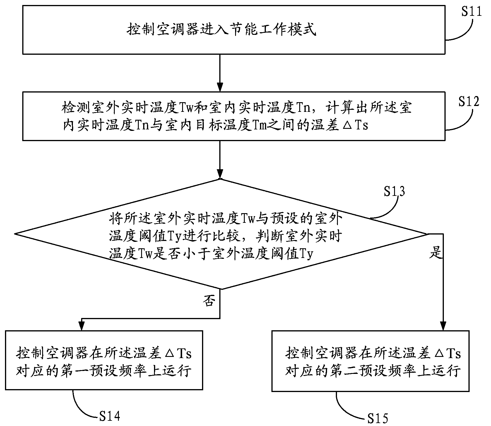
Control method of air conditioner
A control method and air conditioner technology, applied in heating and ventilation control systems, heating methods, space heating and ventilation, etc., can solve problems such as inability to achieve user comfort, energy saving and environmental protection, and the inability of air conditioners to adjust the operating frequency in real time, to achieve Energy Saving Effect
- Summary
- Abstract
- Description
- Claims
- Application Information
AI Technical Summary
Problems solved by technology
Method used
Image
Examples
Embodiment 3
[0040] Embodiment three: see image 3 .
[0041] image 3 The curves S1 and S2 in the figure are respectively the first preset frequency curve and the second preset frequency curve corresponding to each specific temperature difference ΔTs. It can be seen from the figure that corresponding to each temperature difference ΔTs on the abscissa, the points on the first preset frequency curve S1 are larger than the points on the second preset frequency curve S2, and the difference is 15 Hz. That is to say, the difference between the first preset frequency and the second preset frequency is a fixed value, both of which increase with the increase of the temperature difference ΔTs. certainly, image 3 It is not intended to limit the relationship between the phenomenon of the first preset frequency and the second preset frequency increasing as the temperature difference ΔTs increases. image 3 The first preset frequency curve S1 and the second preset frequency curve S2 shown are two ...
Embodiment 4
[0043] Embodiment four: see Figure 4 .
[0044] Figure 4 The curves S1 and S2 in the figure are also the first preset frequency curve and the second preset frequency curve corresponding to each specific temperature difference ΔTs, respectively. Depend on Figure 4 It can be seen from the curve that in the fourth embodiment, corresponding to each temperature difference ΔTs, the first preset frequency and the second preset frequency are in a proportional relationship. The relationship between the two straight lines S1 and S2 in the figure can be expressed as S2= 0.5*S1. The proportionality coefficient may be between 0 and 1, and there is no limitation here, as long as the first preset frequency is greater than the second preset frequency and has a proportional relationship with the second preset frequency.
Embodiment 5
[0045] Embodiment five: see Figure 5 .
[0046] Curve S1 and curve S2 in the figure are also the first preset frequency curve and the second preset frequency curve corresponding to each specific temperature difference ΔTs, respectively. In this embodiment, the curve S2 representing the second preset frequency is a straight line parallel to the abscissa with a slope of zero, that is to say, the second preset frequency here is a fixed frequency value, such as the 20Hz. The first preset frequency curve S1 increases as the temperature difference ΔTs increases, and the greater the temperature difference ΔTs, the greater the first preset frequency.
[0047] The air conditioner control method provided by the present invention can calculate the temperature difference ΔTs between the real-time indoor temperature Tn and the indoor target temperature Tm by detecting the real-time outdoor temperature Tw and the real-time indoor temperature Tn according to the needs of users. As a resu...
PUM
 Abstract
Description
Claims
Application Information
 - R&D
- Intellectual Property
- Life Sciences
- Materials
- Tech Scout
- Unparalleled Data Quality
- Higher Quality Content
- 60% Fewer Hallucinations
Browse by: Latest US Patents, China's latest patents, Technical Efficacy Thesaurus, Application Domain, Technology Topic, Popular Technical Reports.
© 2025 PatSnap. All rights reserved.Legal|Privacy policy|Modern Slavery Act Transparency Statement|Sitemap|About US| Contact US: help@patsnap.com


