
Vascular clamp

A vascular clip and clip technology, applied in the field of vascular clips, can solve the problems of increased pain for patients and increased work intensity of medical staff, and achieve the effects of avoiding secondary injuries, simple structure, and reduced work intensity

Inactive Publication Date: 2013-11-13
THE FIRST AFFILIATED HOSPITAL OF HENAN UNIV OF SCI & TECH
View PDF3 Cites 4 Cited by
  • Summary
  • Abstract
  • Description
  • Claims
  • Application Information

AI Technical Summary

Problems solved by technology

[0002] In clinical practice, direct suture is mostly used for vascular anastomosis. During the operation, the fixation of the broken end of the blood vessel is particularly important to ensure the quality of the entire operation. Common vascular sutures include artery-to-artery and artery-to-meridian. The common forms are end- End suture, end-side suture and side-side suture, blood vessel clips are often used in the blood vessel suture process at present, but the current traditional blood vessel clips are usually provided with two blood vessel clips side by side on a support rod, when needed End-to-side suturing and side-to-side suturing, obviously this kind of vascular clip cannot directly meet the needs of medical staff, increase the work intensity of medical staff and increase pain to patients at the same time

Method used


Image

  • Vascular clamp

Examples


Embodiment Construction

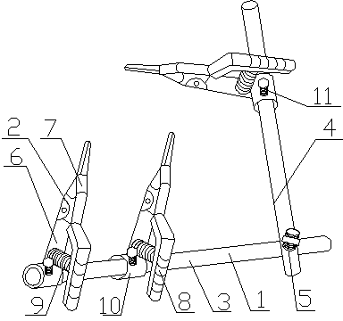
[0012] As shown in the figure, a vascular clip includes a support rod 1 and a plurality of clips 2, the support rod 1 includes a support rod I3 and a support rod II4, and the ends of the support rod I3 and the support rod II4 pass through The pin shaft 5 is rotatably connected, and a plurality of clips 2 are movably connected to the support rod I3 and the support rod II4. The clip 2 includes two clip bodies 6 connected by connecting shafts. The clip body 6 includes The chuck 7 and the handle 8 are connected by a spring 9 between the two handles 8, and a collar 10 is provided at the bottom of one of the handles 8, and the clip 2 is set on the support rod I3 or the support rod II4 through the collar 10, so The handle 8 is provided with anti-slip lines, the collar 10 is provided with a locking device 11, and the locking device 11 is composed of a threaded hole provided on the collar 10 and a bolt matched with the threaded hole, The pin shaft 5 is provided with threads, and the tw...


PUM


Abstract

The invention relates to a vascular clamp which comprises a supporting rod and a plurality of clips. The supporting rod comprises a supporting rod I and a supporting rod II; the tail end of the supporting rod I and the tail end of the supporting rod II are rotationally connected by a hinge pin; both the supporting rod I and the supporting rod II are movably connected with a plurality of clips; each clip comprises two clip bodies connected by a connecting shaft; each clip body comprises a chuck and a handle; every two corresponding handles are connected by a spring; the bottom of one of every two corresponding handles is provided with a collar; and the clips are sleeved on the supporting rod I and the supporting rod II by the collars. According to the invention, the supporting rod I and the supporting rod II are rotationally connected by the hinge pin, so that blood vessels at different angles can be fixed so as to conveniently carry out suture, and thus, the requirements on end-end suture, end-side suture and side-side suture in clinical practice are met and working intensity of medical personnel is reduced; and the clips are all connected with the supporting rod I and the supporting rod II by the collars, so that in the suturing process, different fixing requirements can be met only by rotating the direction of the clips, so that both time and labor are saved.

Description

technical field [0001] The invention relates to the field of medical appliances, in particular to a blood vessel clamp. Background technique [0002] In clinical practice, direct suture is mostly used for vascular anastomosis. During the operation, the fixation of the broken end of the blood vessel is particularly important to ensure the quality of the entire operation. Common vascular sutures include artery-to-artery and artery-to-meridian. The common forms are end- End suture, end-side suture and side-side suture, blood vessel clips are often used in the blood vessel suture process at present, but the current traditional blood vessel clips are usually provided with two blood vessel clips side by side on a support rod, when needed End-to-side suturing and side-to-side suturing, obviously this blood vessel clip can not directly meet the needs of medical staff, increases the work intensity to medical staff and increases pain to the patient simultaneously. Contents of the in...

Claims


Application Information

Patent Timeline
IPC IPC(8): A61B17/00
Inventor 王俊霞张丹丹王俊晓
Owner THE FIRST AFFILIATED HOSPITAL OF HENAN UNIV OF SCI & TECH
Learn More