Eureka AIR delivers breakthrough ideas for toughest innovation challenges, trusted by R&D personnel around the world.

Developing device, image forming apparatus, and method for changing duty ratio

A technology of developing device and duty ratio, which is applied in the direction of electric recording technology using charge pattern, equipment for electric recording technology using charge pattern, and electrography, which can solve the problem of flowing large current and cannot reliably prevent switching elements , without taking into account the flow of large currents and other issues, to achieve the effect of changing the duty cycle

Inactive Publication Date: 2013-10-30
KYOCERA DOCUMENT SOLUTIONS INC
View PDF5 Cites 0 Cited by
  • Summary
  • Abstract
  • Description
  • Claims
  • Application Information

AI Technical Summary

Problems solved by technology

Therefore, if the timing for changing the duty ratio is fixed (same), there is a problem that a large current cannot be reliably prevented from flowing through the switching element.
[0008] In addition, the image forming apparatus realizing a compact hybrid developing device as described above does not take into account that a large current may flow through the switching element when the duty ratio is changed, and cannot solve the above-mentioned problem.

Method used

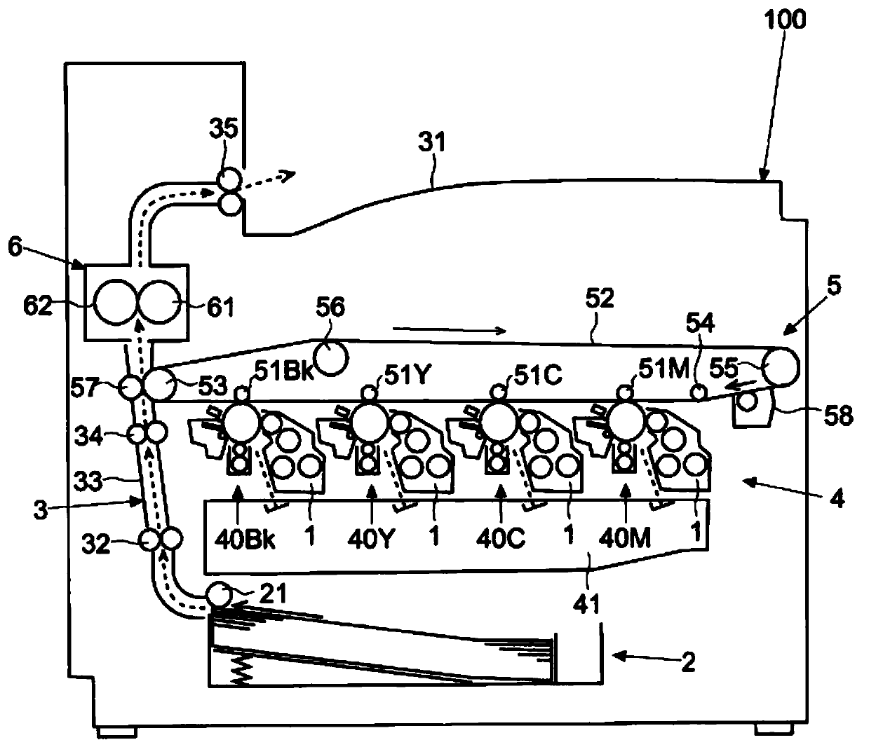
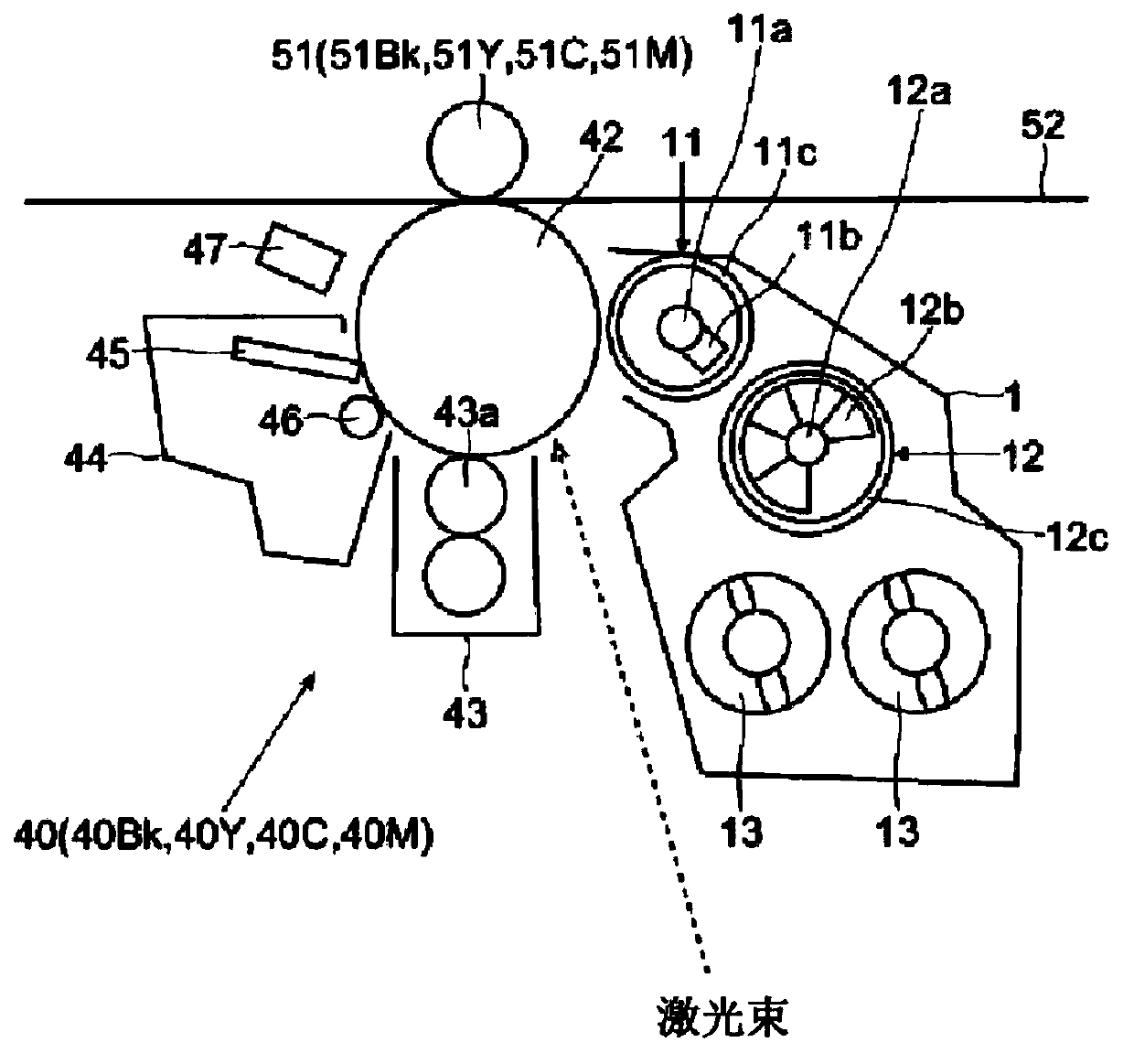
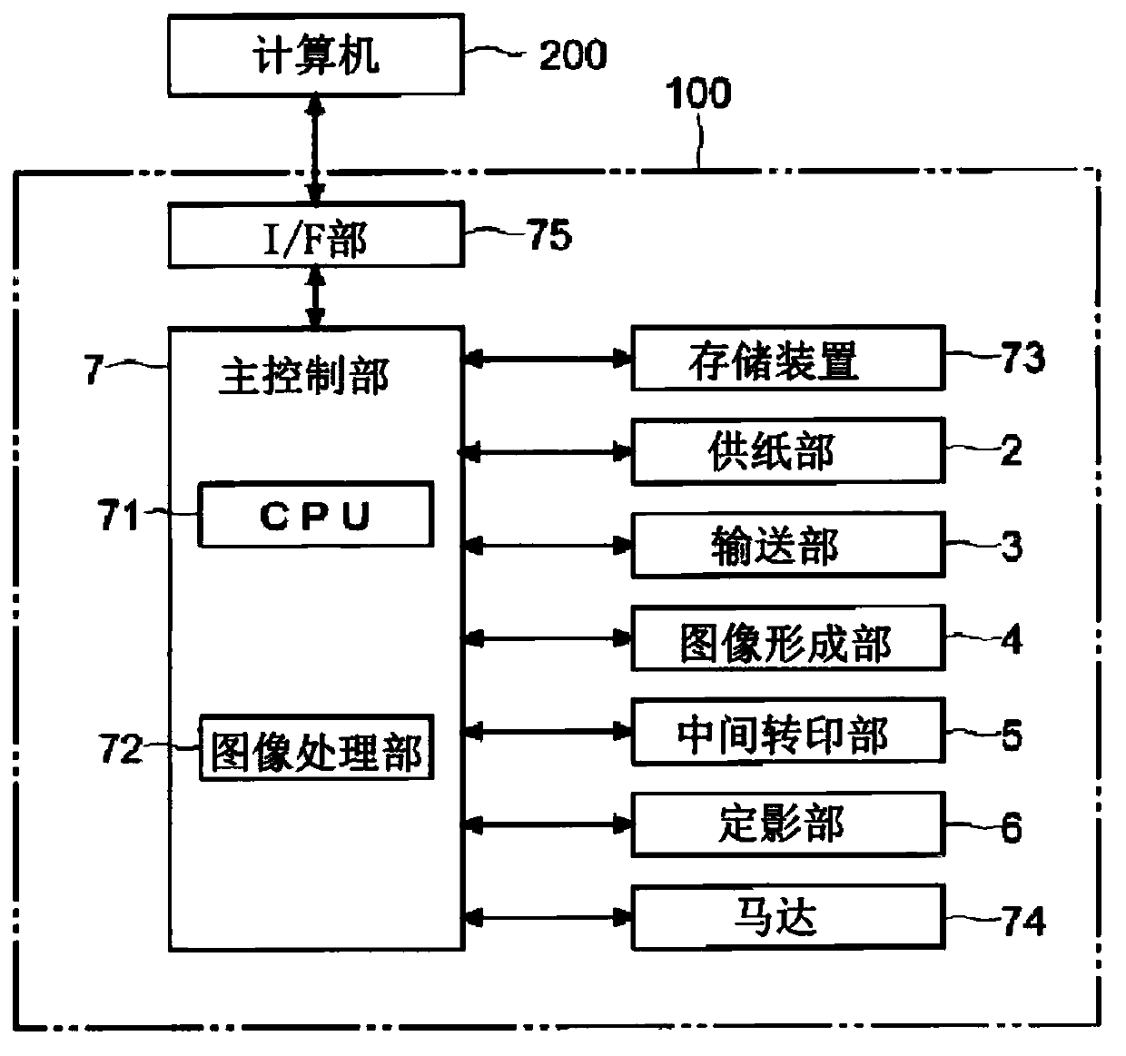

Image

  • Developing device, image forming apparatus, and method for changing duty ratio
  • Developing device, image forming apparatus, and method for changing duty ratio
  • Developing device, image forming apparatus, and method for changing duty ratio

Examples


Embodiment approach )

[0161] Use below Figure 14 , Figure 15 A second embodiment will be described. Figure 14 It is a block diagram showing an example of a configuration for detecting the temperatures of the capacitor 81 and the transformer 82 . Figure 15 It is an explanatory diagram showing an example of temperature characteristic data used to obtain a resonance period.

[0162] In the second embodiment, the temperature of the capacitor 81 and the transformer 82 are detected separately, and the resonance cycle L1 of the series circuit 86 (fluctuation cycle L1 of the voltage between the electrodes of the capacitor 81 ) is obtained based on the detected temperatures of the capacitor 81 and the transformer 82 . The first embodiment is different. Other aspects can be the same as the first embodiment. Therefore, the description in the first embodiment is referred to for the part common to the first embodiment, and description and illustration are omitted.

[0163]First, in the developing devic...


PUM


Abstract

A developing device includes a developing roller, a magnetic roller, a capacitor, a transformer, a switching section, a control section, a temperature detecting section, and a storage section. When changing the duty ratio of a control signal in multiple sequential steps, the control section determines the resonance period based on the temperature and temperature characteristic data and changes the duty ratio of the control signal to the next step during a changing time slot which is one of the first and second halves of a period of voltage fluctuation of the capacitor based on the determined resonance period, the one half in which the current flowing through the switching section is smaller than in the other half of the period.

Description

technical field [0001] The present invention relates to a developing device for performing an electrostatic latent image using toner, an image forming device including the developing device, and a duty ratio changing method. Background technique [0002] In image forming apparatuses such as multifunction machines, copiers, printers, and facsimile machines, there is an apparatus that develops and prints an electrostatic latent image formed on a photoreceptor drum with toner. Furthermore, some image forming apparatuses use a developer (so-called two-component developer) including a magnetic carrier and toner. However, in the development using the two-component developer, if the magnetic brush formed of the carrier is directly brought into contact with the photoreceptor drum, it is not satisfactory in various aspects such as image quality. Therefore, there is an image forming apparatus including a developing device having a developing roller facing a photoreceptor drum and car...

Claims


Application Information

Patent Timeline
Patent Type & Authority Applications(China)
IPC IPC(8): G03G15/08G03G15/09G03G15/00G03G21/20
CPCG03G15/065
Inventor 中川达也
Owner KYOCERA DOCUMENT SOLUTIONS INC
Why Eureka
Eureka Blog
Learn More