


Quick Research
Generate reliable direction feasibility study reports for your R&D in just a few steps.

Technical Q&A
Discover and master advanced knowledge NOW. Basics, ideas, possibilities, all at once.

Find Solutions
As an expert in R&D theories, this can generate solutions to your technical problems instantly.

Evaluate Feasibility
Analyze your overall solution with one click, know your potential R&D risks in advance.

Monitor Landscape
Get weekly tech updates, stay abreast of the latest tech innovations and key insights.
Positive displacement pump assembly with movable end plate for rotor face clearance control
A positive displacement pump and component technology, applied in the field of positive displacement pump components, can solve problems such as air leakage and inefficiency of positive displacement air pumps
- Summary
- Abstract
- Description
- Claims
- Application Information
AI Technical Summary
Problems solved by technology
Method used
Image

Examples
Embodiment Construction
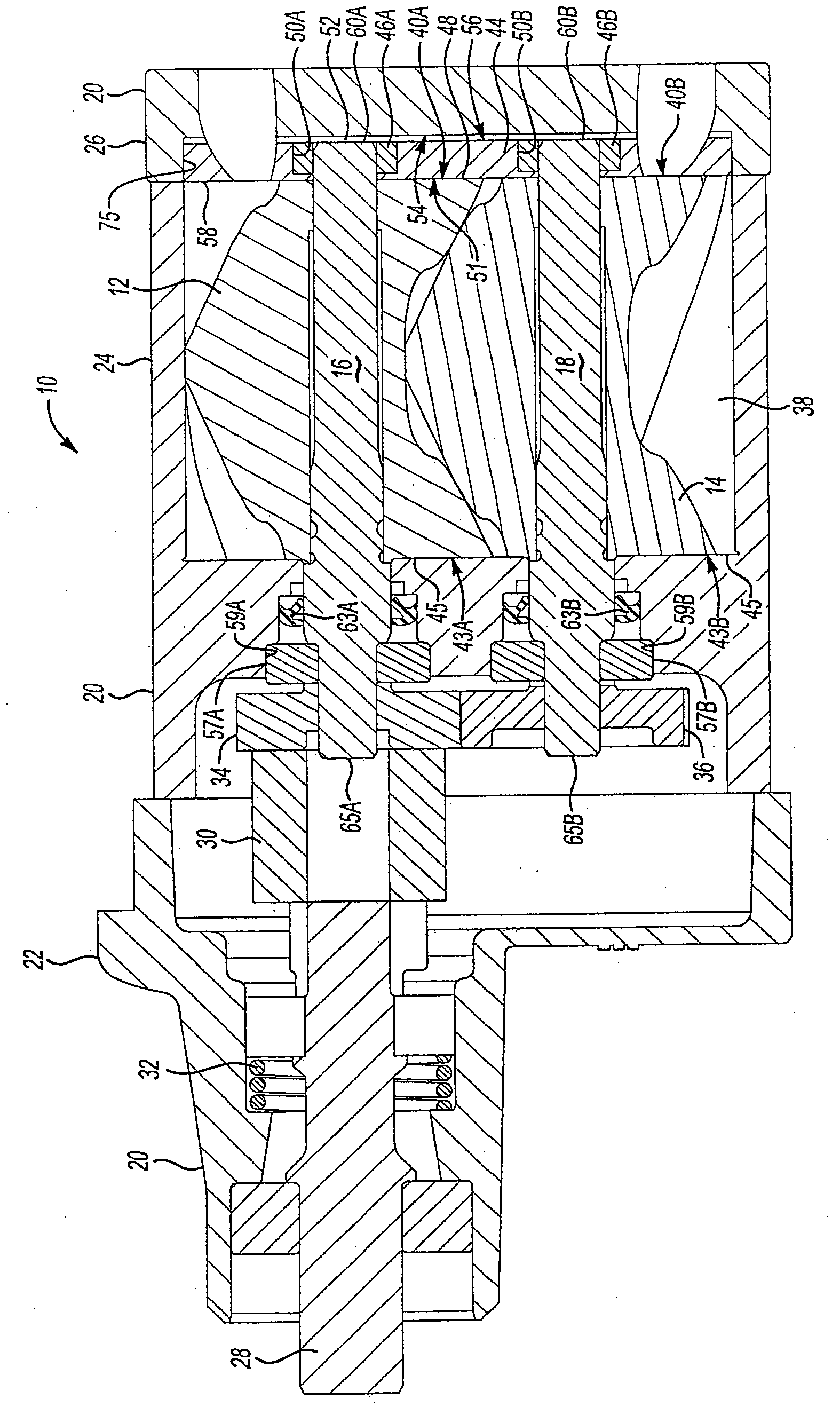
[0014] Referring to the drawings, wherein like reference numerals indicate like components throughout the views, figure 1 A positive displacement pump assembly 10 is shown. In this embodiment, the positive displacement pump assembly 10 is a supercharger assembly for an engine, but the positive displacement pump assembly 10 may be used for pumping other fluids and in other applications. The positive displacement pump assembly 10 has a first rotor 12 meshing with a second rotor 14 . Each rotor 12, 14 has a plurality of lobes. The first rotor 12 is mounted on and rotates with the first rotor shaft 16 . The second rotor 14 is mounted on and rotates with a second rotor shaft 18 , which is generally parallel to the first rotor shaft 16 .
[0015] The rotors 12 , 14 and rotor shafts 16 , 18 are housed within a multi-component positive displacement pump housing 20 . The housing 20 includes a front cover 22 , a middle portion 24 , which may be referred to as a rotor housing portion...
PUM
 Abstract
Description
Claims
Application Information
 - R&D Engineer
- R&D Manager
- IP Professional
- Industry Leading Data Capabilities
- Powerful AI technology
- Patent DNA Extraction
Browse by: Latest US Patents, China's latest patents, Technical Efficacy Thesaurus, Application Domain, Technology Topic, Popular Technical Reports.
© 2024 PatSnap. All rights reserved.Legal|Privacy policy|Modern Slavery Act Transparency Statement|Sitemap|About US| Contact US: help@patsnap.com