
Telescopic boom and crane with the telescopic boom

A telescopic boom and crane technology, applied to cranes and other directions, can solve the problems of long time consumption, high installation cost, and poor micro-movement, and achieve the effects of convenient disassembly and assembly, control of installation cost, and improvement of assembly efficiency

Active Publication Date: 2013-10-30
XUZHOU HEAVY MASCH CO LTD
View PDF7 Cites 0 Cited by
  • Summary
  • Abstract
  • Description
  • Claims
  • Application Information

AI Technical Summary

Problems solved by technology

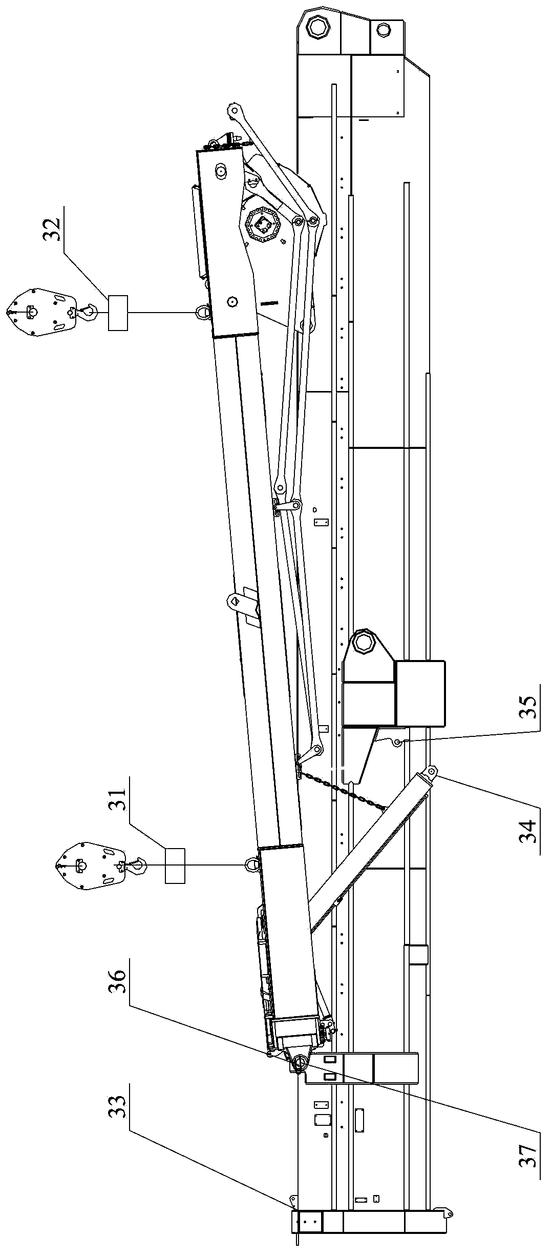
[0004] like image 3 As shown, the super-lifting device assembly method requires the use of two auxiliary cranes, which are used to lift the super-lifting device smoothly through the spreader 31 and the spreader 32 respectively, and slowly move to the top of the basic boom section 33, and the lower hinge point 34 of the luffing cylinder Bypass the box-shaped structure above the hinge point hole 35 of the basic arm, and drop to the bottom of the hinge point hole 35; then, the hinge point hole 36 and the hinge point hole 37 are aligned through repeated adjustments in the front, rear, left, and right directions of the auxiliary crane. This process is time-consuming and laborious. , during the centering process, the height of the lifting device 32 should be slightly higher than that of the lifting device 31, so that the overall super-lifting device is inclined (the hoisting end is upturned), so that the main hinge point hole is centered and the shaft is threaded; the hinge point hole 36 and After the hinge point hole 37 is fixed by the shaft, remove the spreader 31, lift the lower hinge point 34 of the superlift luffing cylinder with the auxiliary crane
Due to the poor micro-movement of the auxiliary crane, the overall assembly process takes a long time; in addition, two auxiliary cranes must be used for assembly, and the installation cost is high

Method used


Image

  • Telescopic boom and crane with the telescopic boom
  • Telescopic boom and crane with the telescopic boom
  • Telescopic boom and crane with the telescopic boom

Examples


Embodiment Construction

[0030] The core of the present invention is to provide a crane telescopic arm with an optimized structure, which can effectively improve the assembly efficiency of its super-lifting device through the arrangement of positioning components, and can effectively control the installation cost at the same time. The present embodiment will be described in detail below in conjunction with the accompanying drawings.

[0031] See Figure 4 , which is a schematic diagram of the overall structure of the telescopic boom of the crane described in this embodiment. This figure does not show the expanded state of the sequentially nested and connected telescopic boom sections, so as to clearly show the relative positional relationship between the positioning member and the basic boom sections in this solution.

[0032] Relatively speaking, the main hinge point hole 11 for hinged with the hinged end of the superlift device 20 is located at the front of the basic jib section 10, and is used for...


PUM


Abstract

The invention discloses a telescopic boom. A basic jib is provided with a main hinge point hole of a superlift device and a hinge pint hole of a variable amplitude oil cylinder; the telescopic boom also comprises a first positioning block and a second positioning block; the first positioning block is arranged on the basic jib at the lower part of the front side of the main hinge point hole; a side of the first positioning block adjacent to the main hinge point hole is provided with a first concave arc positioning face; the first concave arc positioning face adapts to an outer convex arc surface of a hinged end of the superlift device and is concentric with the main hinge point hole; the second positioning block is arranged on the basic jib below the rear side of the hinge point hole of the variable amplitude oil cylinder; a side, of the second positioning block, adjacent to the main hinge point hole of the variable amplitude oil cylinder is provided with a second concave arc positioning face; the second concave arc positioning face adapts to an outer convex arc surface of a hinged end of the variable amplitude oil cylinder, and is concentric with the hinge point hole of the variable amplitude oil cylinder. Accordingly, the telescopic boom can greatly reduce the installation cost while improving the assembly efficiency. Accordingly, the telescopic boom can greatly reduce the installation cost while improving the assembly efficiency. On this basis, the invention also provides a crane provided with the telescopic boom.

Description

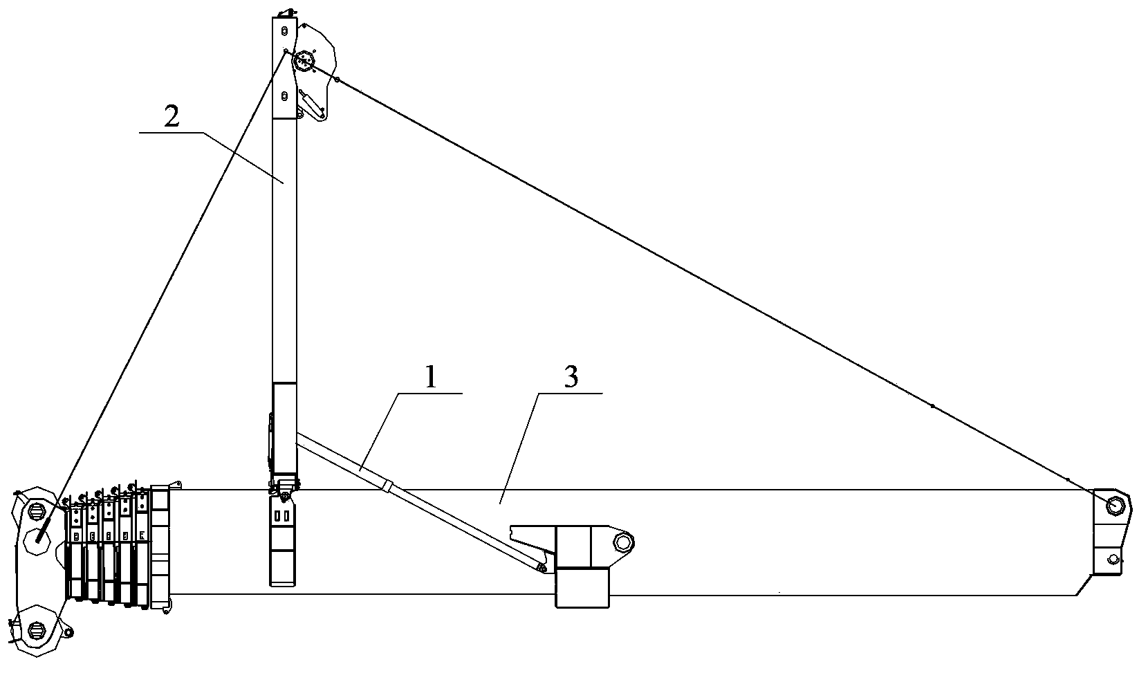
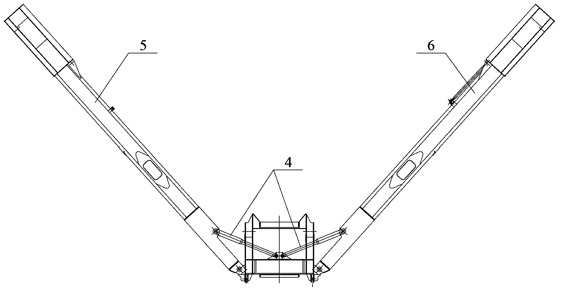
technical field [0001] The invention relates to the technical field of engineering machinery, in particular to a telescopic arm and a crane with the telescopic arm. Background technique [0002] With the continuous development of the world economy, large-scale infrastructure projects such as wind power and large-scale petrochemicals are increasing, and super-large-tonnage all-terrain cranes are favored by the market for their flexible movement, rapid transition, and quick operation. At the same time, the performance requirements for super-large-tonnage cranes are getting higher and higher, and the importance of its super-lifting device to improve the performance of super-large-tonnage cranes is also becoming more and more obvious. [0003] See figure 1 with figure 2 ,in, figure 1 It is a schematic diagram of the overall structure of the existing superlift device, figure 2 yes figure 1 Schematic diagram of the cooperative relationship between the left and right arms of...

Claims


Application Information

Patent Timeline
Patent Type & Authority Applications(China)
IPC IPC(8): B66C23/687B66C23/82
CPCB66C23/828
Inventor 佟雪峰兰天杨敏王小强
Owner XUZHOU HEAVY MASCH CO LTD
Learn More