
Power slide device for vehicle seat

A technology for vehicle seats and sliding devices, which is applied to vehicle seats, special positions of vehicles, movable seats, etc., and can solve problems such as screw deformation

Inactive Publication Date: 2013-10-30
SHIROKI KOGYO CO LTD
View PDF6 Cites 4 Cited by
  • Summary
  • Abstract
  • Description
  • Claims
  • Application Information

AI Technical Summary

Problems solved by technology

[0009] However, when the aforementioned inertial force caused by a collision of a vehicle equipped with the power slide device is large (ie, greater than the aforementioned predetermined value), the connecting portion between the fixed portion 06 and the rear orthogonal plate portion 07 is plastically deformed , so that the rear orthogonal plate portion 07 is tilted forward with respect to the connecting portion, thereby causing deformation of the lead screw 03 supported by the rear orthogonal plate portion 07

Method used


Image

  • Power slide device for vehicle seat
  • Power slide device for vehicle seat
  • Power slide device for vehicle seat

Examples


Embodiment Construction

[0044] The described directions in the following description are defined as directions according to the arrows shown in the figures.

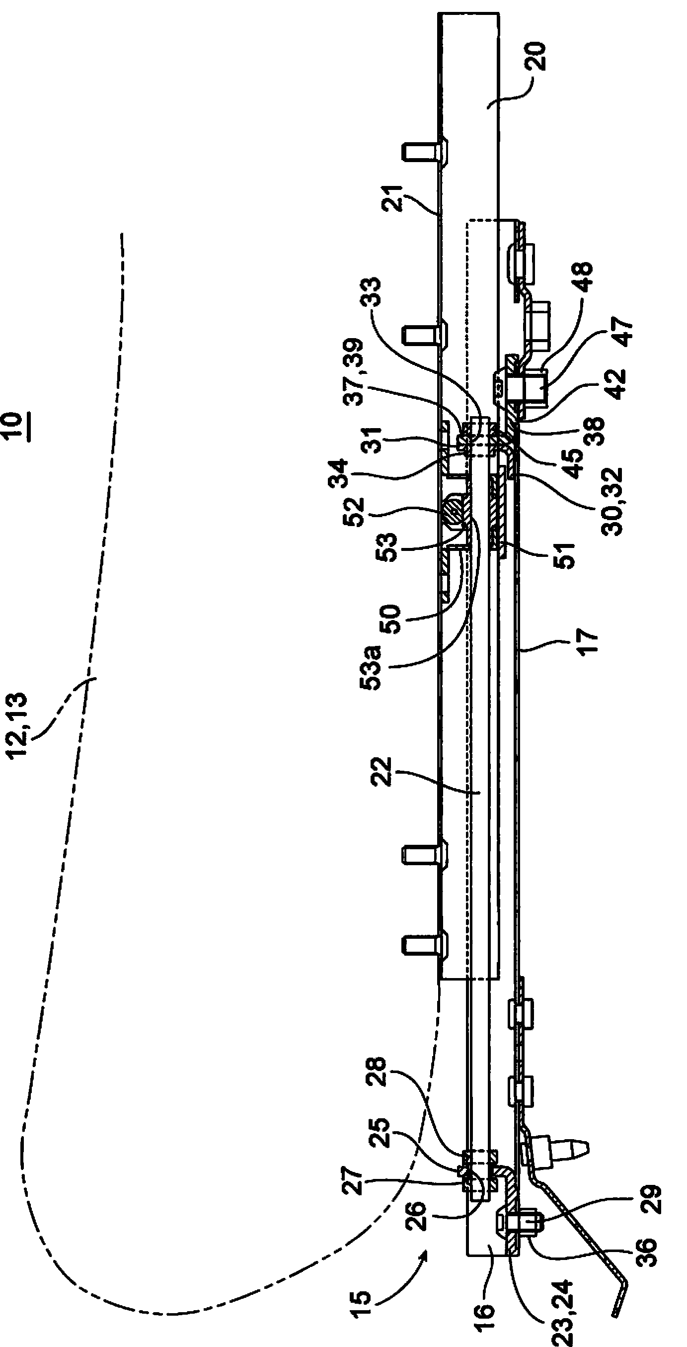
[0045] exist figure 1 The vehicle seating arrangement 10 shown in is provided with a seat 12 and a power slide 15 which is secured to the vehicle floor panel and supports a cushion 13 of the seat 12 .

[0046] The power slide 15 is provided with a pair of left and right lower rails 16 which are fixed to the vehicle floor panel via a pair of front and rear brackets (not shown) and extend in the forward / rearward direction, and the power slide 15 is further provided with a pair of left and right lower rails 16 . The upper rails 20 are respectively mounted to the pair of lower rails 16 so as to be slidable on the lower rails 16 . Each of the lower rails 16 is a channel member made of metal, the upper side of which is open. Each lower rail 16 is provided at its bottom with a floor portion 17 having the shape of a horizontal plate, which is fixed ...


PUM


Abstract

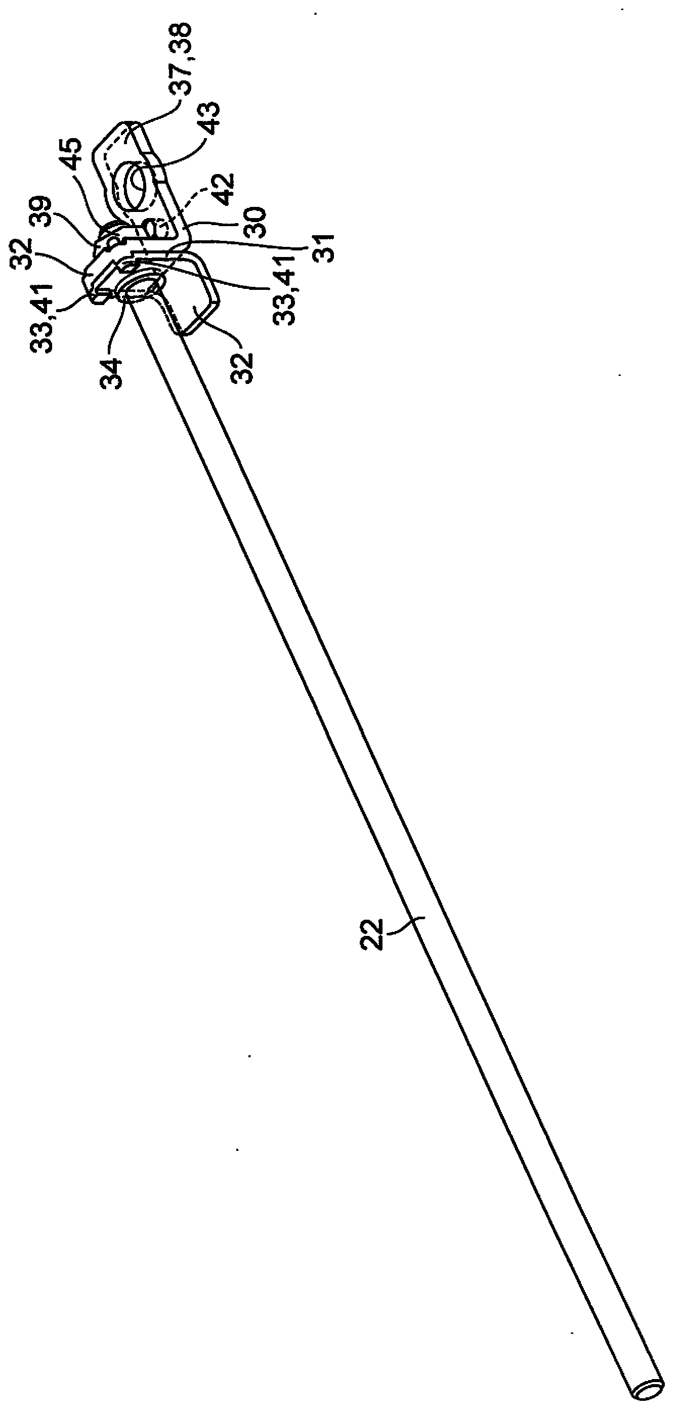
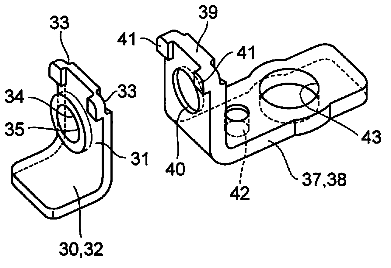
A power slide device (15) for a vehicle seat includes a lower rail (16) and an upper rail (20) slidable relative to the lower rail, a front support member (23) fixed to the lower rail, a screw rod (22), a rear support member (37) provided with a rear orthogonal plate portion (39) and a fixed plate portion (38), a movement limiter (45) which limits movement of the screw rod, a worm wheel (53), and a collision load receiving portion (32) which limits forward tilting of the rear orthogonal plate portion by contacting the base surface of the lower rail when a force is exerted on the screw rod forwardly from the worm wheel. The collision load receiving portion (32) is positioned in front of the rear orthogonal plate portion and is spaced downward from the screw rod and integrated with the rear support member that is mounted to the screw rod.

Description

technical field [0001] The present invention relates to a power sliding device for a vehicle seat. Background technique [0002] Figure 9 A power slide device for a vehicle seat according to the related art is shown. [0003] The power sliding device is provided with a lower rail 01 , an upper rail 02 , a lead screw 03 and a gear box 04 . The lower rail 01 is fixed to the vehicle floor and in the forward / rearward direction (relative to Figure 9 The upper rail 02 is slidable in the forward / rearward direction relative to the lower rail 01, the lead screw 03 is fixed to the lower rail 01 and extends in the forward / rearward direction, and the gear box 04 is fixed to the upper rail 02. The gearbox 04 is equipped with a worm gear (not shown) that is rotated by the driving force of an electric motor (not shown). The lead screw 03 is screwed into an internally threaded hole formed in the worm gear as a through hole extending in the forward / rearward direction. [0004] A front s...

Claims


Application Information

Patent Timeline
IPC IPC(8): B60N2/07B60N2/90
CPCB60N2/0722B60N2/0727B60N2/4249B60N2/0715B60N2/067
Inventor 榎嶋友宏
Owner SHIROKI KOGYO CO LTD
Learn More