
Impeller and aerator with impeller

A technology of aerator and impeller, which is applied in fish farming, application, animal husbandry and other directions, can solve problems such as affecting the effect of aeration, and achieve the effects of good product consistency, high production efficiency and simple machining.

Active Publication Date: 2013-10-30
ZHEJIANG FORDY MACHINERY
View PDF10 Cites 7 Cited by
  • Summary
  • Abstract
  • Description
  • Claims
  • Application Information

AI Technical Summary

Problems solved by technology

The impeller of the impeller type aerator has metal welded impeller and plastic impeller. Most of the plastic impellers are assembled, and there are also integral injection molded impellers. There are multiple blades on the outside of the cone. The blades and the cone are combined obliquely. The end face is of the same height, the water flow spreads around when working, and the water splash is not high enough to affect the oxygenation effect

Method used


Image

  • Impeller and aerator with impeller
  • Impeller and aerator with impeller
  • Impeller and aerator with impeller

Examples


Embodiment Construction

[0039] The present invention will be further described below with specific embodiment, see Figure 1-17 :

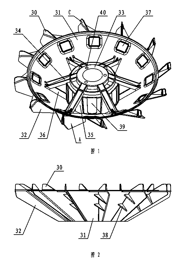
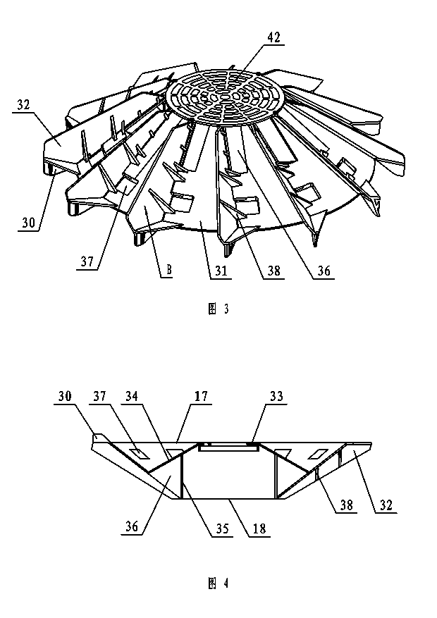
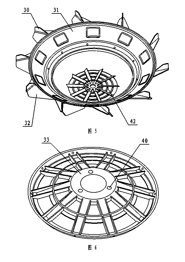
[0040] An impeller, including a cone 31, blades 32, and a fixed seat 33, the impeller is injection molded at one time, the upper end of the cone 31 is 17 large and the lower end 18 is small, the fixed seat 33 is inside the cone 31, and the fixed seat 33 has a connection with the aerator The flange 44 of the output shaft matches the connecting hole 40. There are a plurality of blades 32 on the outside of the cone 31. The blades 32 and the cone 31 are obliquely combined. The water board 30, the working surface C of the paddle board and the working surface A of the blade make a smooth transition, and the water driven by the blade 32 flows through the working surface C of the paddle board and splashes upwards, so that the water splash increases, the water body diverges, and the connection with the air is increased. Improve the oxygenation effect.

[0041] The conical body ...


PUM


Abstract

The invention relates to an impeller which comprises a tapered body, a plurality of blades and a fixing seat. The impeller is formed by one-time injection moulding, the fixing seat is positioned in the tapered body, connecting holes matched with a flange of an output shaft of an aerator are formed in the fixing seat, the blades are arranged on the outer side of the tapered body and are obliquely combined with the tapered body, thrashing plates basically vertical to the upper end face of the tapered body are arranged at the upper end of the outer side of the tapered body, and smooth transition is realized between working faces C of the thrashing plates and working faces A of the blades. Water flow driven by the blades splashes upwards through the working faces C of the thrashing plates to enable water splash to rise and enable a water body to disperse, so that contact surface with the air is increased to improve aeration effect. The weight of an alloy-aluminum pressure-casted speed reducing box is greatly reduced, and a small-size flat floating ball can be arranged at the other end of a supporting end to enable the aerator to keep afloat, so that a flat surface is enable to be relatively parallel to the water flow direction during working of the aerator, resistance of a floating body on the water flow during working of the aerator is reduced, and aeration efficiency is improved.

Description

technical field [0001] The invention relates to an aerator, in particular to an impeller and an aerator with the impeller, belonging to fish farming machinery. Background technique [0002] The aerator is a life-saving and stimulating equipment for fish and shrimp in aquaculture. Existing mechanical aerators mainly include three types: water wheel type, impeller type and water spray type, among which the impeller type aerator is the most widely used. The impeller of the impeller type aerator has metal welded impeller and plastic impeller. Most of the plastic impellers are assembled, and there are also integral injection molded impellers. There are multiple blades on the outside of the cone. The blades and the cone are combined obliquely. The end face is of the same height, and the water flow spreads around when working, and the water splash is not high enough to affect the oxygenation effect. Contents of the invention [0003] The purpose of the present invention is to o...

Claims


Application Information

Patent Timeline
Patent Type & Authority Applications(China)
IPC IPC(8): A01K63/04
Inventor 吴为国
Owner ZHEJIANG FORDY MACHINERY
Learn More