Ethernet power supply input structure of wireless network protector

An input structure, wireless network technology, applied in data switching current source, data exchange details, etc., can solve the problems of high cost, cluttered wiring, complicated cable deployment and installation, etc., to achieve the effect of low design cost and convenient use

Inactive Publication Date: 2013-10-23
SUZHOU IND PRAK NEW HONGBO COMM TECH
View PDF4 Cites 2 Cited by
  • Summary
  • Abstract
  • Description
  • Claims
  • Application Information

AI Technical Summary

Problems solved by technology

[0003] In traditional network construction, all terminal devices are directly powered by the power networ...

Method used


Image

  • Ethernet power supply input structure of wireless network protector

Examples


Embodiment Construction

[0015] The present invention is further elaborated below by way of specific embodiments:

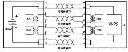
[0016] This embodiment provides a power-over-ethernet input structure for a wireless network protector. The power-over-ethernet input structure includes a protector and a power supply connected to the input end of the protector. A line is arranged between the protector and the power supply cables.

[0017] The protector includes a first signal transmission module and a first signal receiving module, and the power supply includes a second signal transmission module and a second signal receiving module; the first signal transmission module is connected to the second signal receiving module, and the first signal The receiving module is connected with the second signal transmission module.

[0018] The cable includes at least a first current transmission pair and a second current transmission pair. Both the first current transmission pair and the second current transmission pair are connect...


PUM


Abstract

The invention provides an Ethernet power supply input structure of wireless network protector. The Ethernet power supply input structure comprises a protector and a power supply source which is connected with an input terminal of the protector; and a cable is arranged between the protector and the power supply source. The Ethernet power supply input structure of the wireless network protector, according to the invention, has advantages of low cost, and convenient and simple use.

Description

technical field [0001] The invention relates to an Ethernet power supply input structure of a wireless network protector, in particular to an Ethernet power supply input structure of a wireless network protector that does not directly supply power from a power network and adopts the Ethernet power supply technology. Background technique [0002] China's communication market ushered in 3G technology application licenses in 2008: China Mobile's TD-SCDMA, China Telecom's CDMA2000, and China Unicom's WCDMA. As a mobile communication technology, 3G has the advantages of wide coverage and high-speed mobile support, but the rate is relatively low, while WLAN (Wireless Local Area Network) has a relatively high rate and narrow coverage compared to 3G. 3G and WLAN are highly complementary of the two technologies. Operators accelerated the application of Wi-Fi technology, introduced the application mode of 3G+WLAN, and began to build WLAN systems on a large scale. WLAN products are b...

Claims


Application Information

Patent Timeline
IPC IPC(8): H04L12/10
Inventor 胡进
Owner SUZHOU IND PRAK NEW HONGBO COMM TECH
Why Eureka
Try Eureka