Electric connector assembly, plug type connector and socket type connector

A plug-type connector, electrical connector technology, applied in the direction of two-part connection device, parts of the connection device, connection, etc., can solve the problem that the board surface is easily damaged, the clamping margin is reduced, and the clamping part is not elastic problems, to achieve easy results

Active Publication Date: 2013-10-23
HIROSE ELECTRIC GROUP
View PDF7 Cites 14 Cited by
  • Summary
  • Abstract
  • Description
  • Claims
  • Application Information

AI Technical Summary

Problems solved by technology

[0015] In addition, the above-mentioned locking part itself is formed as a relatively short wrist because it extends along the height direction of the above-mentioned end part. Furthermore, its shape is folded back into an inverted U shape by close contact, so the rigidity is high. The locking part itself is almost no elasticity
And, the above-mentioned inverted U-shaped locking part is engaged with the surface of the fixing part of the plug connector by the front end edge part of the inverted U-shaped part, so in order for the front end edge part to be reliably engaged with the above-mentioned engaging part , the front end edge part must make the above-mentioned surface abut and move, and the above-mentioned surface is easy to be damaged by the tapered area of ​​the front end edge part before the engaging position
Furthermore, the locking portion of the fixing part of the plug connector is the same as the locking part of the fixing part of the above-mentioned receptacle connector, and is formed on a shorter arm body extending in the height direction, so the elasticity of the arm body The amount of deformation cannot be guaranteed to be large, so it is difficult to avoid damage
[0016] Furthermore, in the fixing part related to Patent Document 2, except that the amount of elastic deformation is not large, the cross-section in the thickness direction or the tapered front edge part abuts and engages with the plate surface of the fixing part, so the above-mentioned plate The surface is easily damaged, and as a result, the engagement margin decreases due to wear, and the locking function tends to decrease

Method used


Image

  • Electric connector assembly, plug type connector and socket type connector
  • Electric connector assembly, plug type connector and socket type connector
  • Electric connector assembly, plug type connector and socket type connector

Examples


Embodiment Construction

[0050] Hereinafter, embodiments of the present invention will be described based on the drawings.

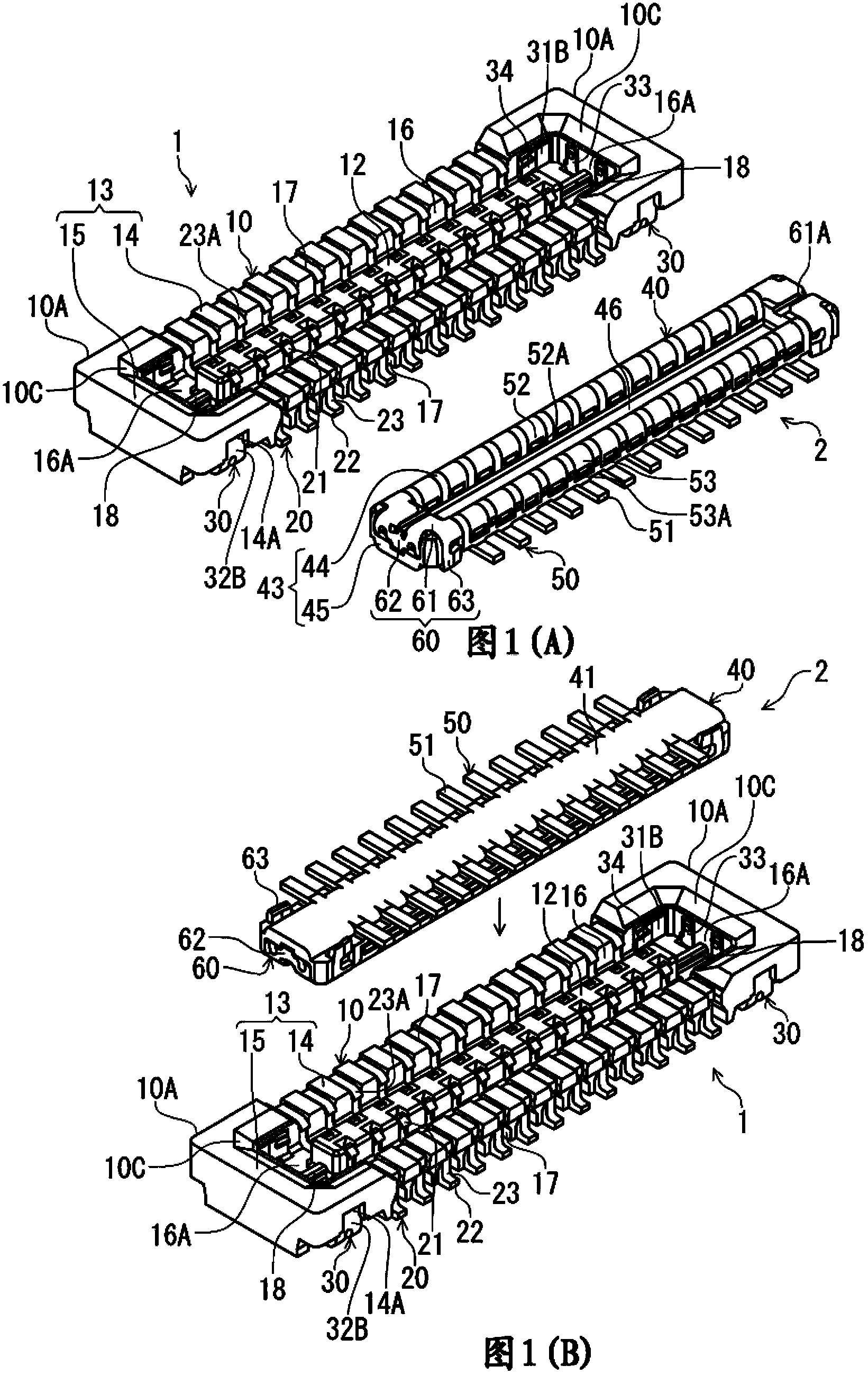
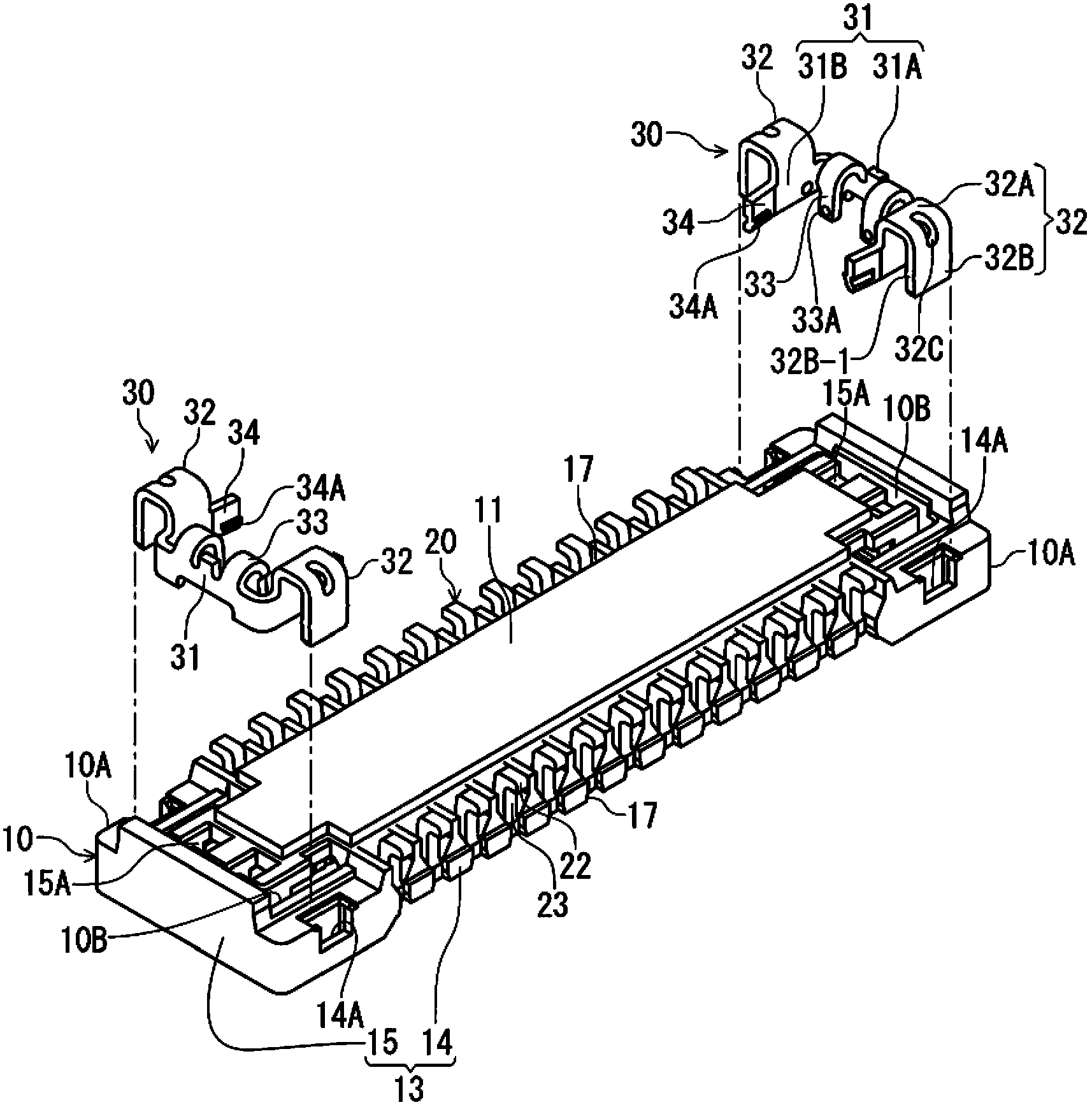
[0051] 1(A) and FIG. 1(B) are perspective views showing the whole of the receptacle connector and the plug connector according to this embodiment, and FIG. 1(A) makes the receiving spaces of the two connectors face up. Indicates that Fig. 1(B) shows the posture just before the two connectors are mated. figure 2 It is a perspective view of the receptacle connector of Fig. 1(A) and Fig. 1(B), showing the state before the locking parts are assembled. in the figure 2 1 (A) and FIG. 1 (B) are represented by reversing the receptacle connector up and down. image 3 It is a perspective view of the plug connector in Fig. 1, showing the state before the locking parts are assembled.

[0052] The receptacle connector 1 and the plug connector 2 of the present embodiment are connectors for circuit boards arranged on the mounting surfaces of different circuit boards (not shown), respectivel...


PUM


Abstract

The present invention provides an electric connector assembly, a plug type connector and a socket type connector. The electric connector assembly has a socket type connector and a plug type connector engaged with the socket type connector, wherein an engaging part of a casing of the plug type connector has a structure difficult to damage. The plug type connector (2) has a reinforcing component (60) arranged at an end part of the engaging part in a terminal arrangement direction, wherein the reinforcing component is made by bending a metal plate used as a component, and the reinforcing component comprises: a base part (61) for covering a lower surface of the end part of the engaging part through a board which is orthogonal to a connector plugging direction as the engaging part of the plug type connector (2) is downward; a side plate part (63) for covering two side surfaces of the end part through boards which are respectively parallel to the terminal arrangement direction and the connector plugging direction; and an end plate part for covering an end surface of the end part through a board which is orthogonal to the terminal arrangement direction.

Description

technical field [0001] The present invention relates to an electrical connector assembly having a receptacle connector disposed on a circuit board and a plug connector disposed on another circuit board and fitted and connected to the receptacle connector, and one of the components constituting the assembly A plug connector and a receptacle connector constituting the other side of the assembly. Background technique [0002] For example, Patent Document 1 discloses such an electrical connector assembly. In this patent document 1, the housing of the receptacle connector is formed in a shape surrounded by a peripheral wall rising from the bottom wall and extending in the terminal arrangement direction from a bottom wall facing the circuit board. Furthermore, between the protruding wall portion and the peripheral wall, a quadrangular annular space opened upward is formed as a receiving space for receiving the fitting portion of the plug connector. On the other hand, the housing...

Claims


Application Information

Patent Timeline
Patent Type & Authority Applications(China)
IPC IPC(8): H01R13/46H01R13/627H01R24/00
CPCH01R13/629H01R13/639H01R24/00
Inventor 绿川和弥
Owner HIROSE ELECTRIC GROUP
Why Eureka
Try Eureka