Solar battery

A technology for solar cells and electrodes, applied in the field of solar cells, can solve the problems of high series resistance, poor conductivity, and limitations of cells, and achieve the effect of improving conversion efficiency, good conductivity and good quality

Inactive Publication Date: 2016-02-17
MOTECH INDUSTRIES
View PDF5 Cites 0 Cited by
  • Summary
  • Abstract
  • Description
  • Claims
  • Application Information

AI Technical Summary

Problems solved by technology

[0008] Although Figure 5 , Image 6 The improved structure helps to reduce the cavity ratio of the linear through-hole battery, but if blindly reducing the area occupied by the back electrode 15 to limit the diffusion of silicon, the area of ​​the back electrode 15 will be too small, which will lead to The electrode conductivity is not good, the series resistance of the battery is too high, and in Figure 5 , Image 6 In this case, the current between two adjacent conductive segments 157 cannot be directly transmitted, but can only be conducted to the main grid line 153 through the conductive segments 157, so the current transmission is limited and the conductivity is poor.

Method used


Image

  • Solar battery
  • Solar battery
  • Solar battery

Examples


Embodiment Construction

[0042] The present invention will be described in detail below with reference to the accompanying drawings and embodiments. It should be noted that in the following description, similar elements are denoted by the same numerals.

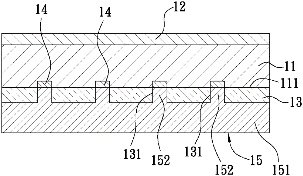
[0043] refer to Figure 7 , Figure 8 , Figure 9 , The first preferred embodiment of the solar cell of the present invention includes: a substrate 2, a dielectric layer 3, at least one through hole 31, a plurality of back electric field structures 4, an electrode 5 and at least one on the dielectric layer 3 and The opening 6 formed surrounded by the electrode 5 .

[0044] The substrate 2 includes a first surface 21 and a second surface 22 opposite to each other. The first surface 21 is a back surface, and the second surface 22 is a light-incident surface, which can be roughened to increase the amount of light incident. The substrate 2 is also provided with an emitter layer 23 located at the second surface 22 and capable of forming a p-n junction wi...


PUM


Abstract

Disclosed is a solar-energy battery including a substrate, a dielectric layer, at least one through hole arranged in the dielectric layer, an electrode arranged on the dielectric layer, an opening, a first area and a second area. The electrode includes a first structure provided with a first conductive section and a second structure arranged in the through hole. The opening is arranged in the dielectric layer and is surrounded by the electrode, wherein the conductive section is arranged in the opening. The first area is a total area of an orthographic projection of the opening on the substrate. The second area, which is larger than the first area, is a total area of an orthographic projection of the electrode on the substrate. The electrode of the solar-energy battery is capable of restraining diffusion of a substrate material so that enough substrate material can be mixed with an electrode material to form a local back surface field with a high thickness and good quality. Therefore, conversion efficiency of the battery is improved.

Description

technical field [0001] The invention relates to a solar cell, in particular to a silicon crystal solar cell with a local back electric field structure. Background technique [0002] refer to figure 1 , is a known solar cell, mainly comprising: a substrate 11, an emitter layer 12 forming a p-n junction with the substrate 11, a dielectric layer 13, and a plurality of back electric field structures formed on local parts of the substrate 11 (local back surface field, LBSF for short) 14 and a back electrode 15 . [0003] The dielectric layer 13 is formed on a back surface 111 of the substrate 11 and has a plurality of circular through holes 131 spaced from front to back, left to right. The back electric field structure 14 is formed on the back surface 111 corresponding to the through hole 131 , and the carrier concentration of the back electric field structure 14 is higher than that of the p-type substrate, which can help improve carrier collection efficiency and photoelectric ...

Claims


Application Information

Patent Timeline
Patent Type & Authority Patents(China)
IPC IPC(8): H01L31/0224H01L31/068
CPCY02E10/547
Inventor 李昆儒林佳玫任志榆方婷
Owner MOTECH INDUSTRIES
Why Eureka
Try Eureka