
Electronic expansion valve

A technology of electronic expansion valve and valve body, which is applied in the direction of valve details, valve device, valve operation/release device, etc. It can solve the problems of changing the installation angle of coil parts, complicated manufacturing process, and small application range, so as to simplify the manufacturing process , reduce manufacturing costs, and have a wide range of applications

Inactive Publication Date: 2013-10-23
ZHEJIANG DUNAN HETIAN METAL CO LTD
View PDF9 Cites 2 Cited by
  • Summary
  • Abstract
  • Description
  • Claims
  • Application Information

AI Technical Summary

Problems solved by technology

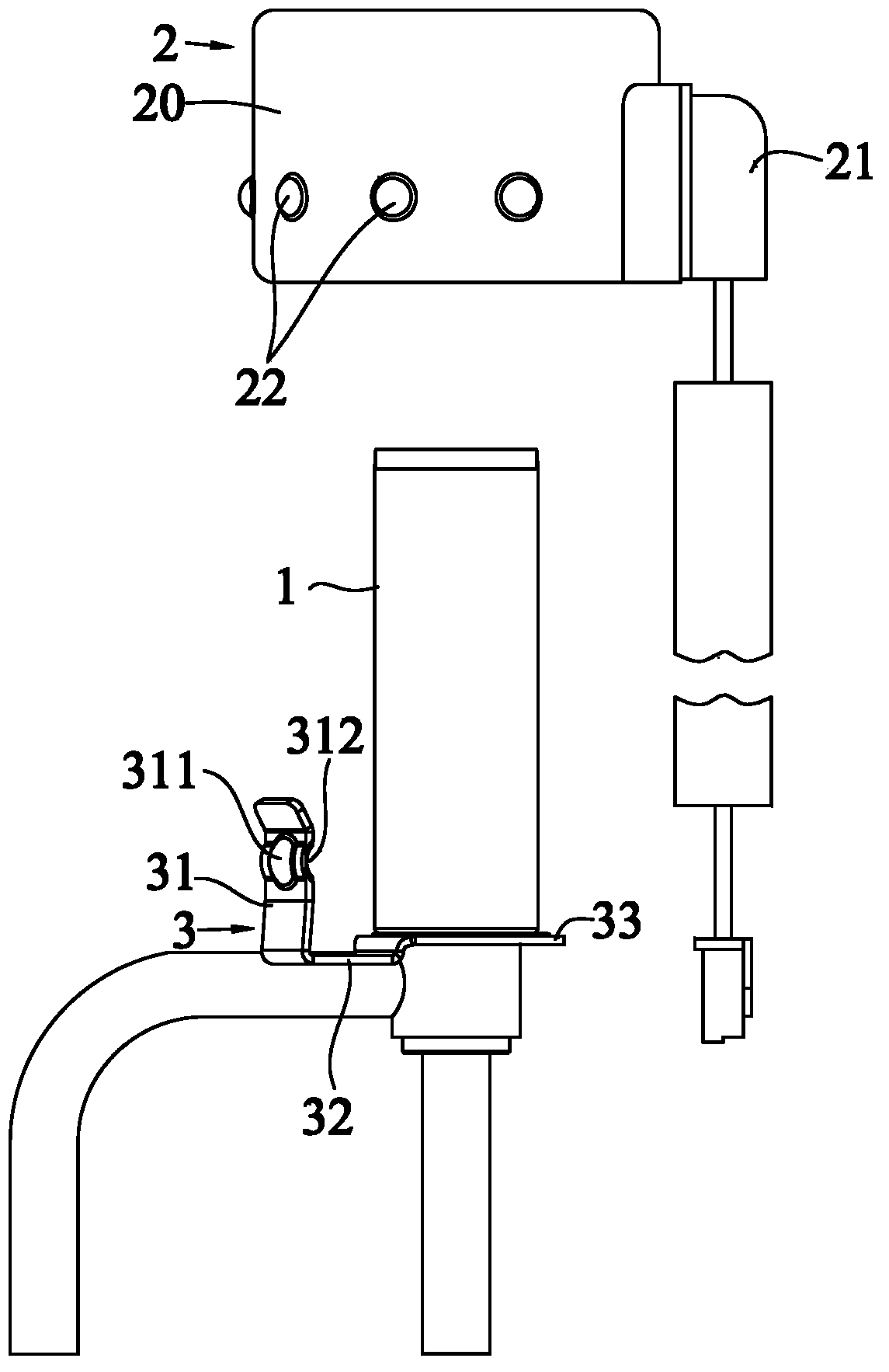
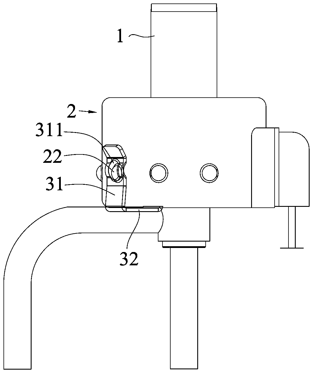
For example, the invention patent with the publication number "102840372" and the name "an expansion valve and its coil" discloses the positioning structure of the above-mentioned coil components, and another example is the publication number "101799087" and the name is "coil connection structure and electronic expansion valve". The positioning structure of the above-mentioned coil parts is also disclosed in the invention patent of "Valve". The expansion valve disclosed by the former cannot change the installation angle of the coil parts according to the installation environment in actual use, and the scope of use is small; the expansion valve disclosed by the latter, although It can realize multi-angle installation of coil parts in the circumferential direction of the valve body, but the positioning structure is relatively complicated. The positioning piece needs to be welded on the valve body, the positioning card is connected to the bottom of the coil, and the positioning piece is then connected to the bending structure on the positioning card. Although this positioning structure has good stability, it has the disadvantages of complicated manufacturing process and inconvenient disassembly and assembly of coil parts.

Method used


Image

  • Electronic expansion valve
  • Electronic expansion valve

Examples


Embodiment Construction

[0022] The present invention proposes an electronic expansion valve, which includes a coil part and a valve body. The coil part is fixed on the valve body through a positioning structure. The positioning structure includes a positioning frame arranged on the valve body and a positioning protrusion arranged on the outer surface of the coil part. The positioning frame includes a fixing part connected to the valve body, a positioning part extending to the outer surface of the coil component, and a support part connecting the positioning part and the fixing part, and the positioning part engages with the positioning protrusion. Compared with the prior art, less auxiliary parts are used for positioning the coil parts, which simplifies the manufacturing process of the electronic expansion valve, reduces parts and manufacturing costs, and at the same time, the improved positioning structure also makes disassembly and assembly of the coil parts more convenient.

[0023] The technical s...


PUM


Abstract

The invention discloses an electronic expansion valve which belongs to the field of refrigerating systems and solves the technical problems that the coil positioning structure of the existing electronic expansion valve is complicated and inconvenient to dismantle and mount. The electronic expansion valve, disclosed by the invention, comprises a coil component and a valve body, wherein the coil component is fixed on the valve body through a positioning structure; the positioning structure comprises a positioning frame and a positioning bulge; the positioning frame is arranged on the valve body, and the positioning bulge is arranged on the external side face of the coil component; the positioning frame comprises a fixed part, a positioning part and a supporting part; the fixed part is connected with the valve body; the positioning part extends to the external side face of the coil component; the supporting part is used for connecting the fixed part with the positioning part; the positioning part is clamped with the positioning bulge.

Description

【Technical field】 [0001] The invention relates to an electronic expansion valve, in particular to an electronic expansion valve used in refrigeration systems such as air conditioners and refrigerators. 【Background technique】 [0002] Refrigeration systems such as air conditioners and refrigerators are mainly composed of compressors, evaporators, condensers and various regulating valve bodies. Taking the electronic expansion valve as an example, the electronic expansion valve mainly includes a valve body and a coil part. The valve body is equivalent to the rotor part of the stepping motor, and the coil part is equivalent to the stator part of the stepping motor. By applying a pulse drive signal to the coil winding, A regular magnetic field is generated on the pole claw of the coil magnetizer, which drives the rotation of the rotor inside the valve body part, thereby adjusting the flow rate at the valve port of the valve body part and realizing the control of the refrigerant f...

Claims


Application Information

Patent Timeline
Patent Type & Authority Applications(China)
IPC IPC(8): F25B41/06F16K31/06F25B41/31
CPCY02B30/72Y02B30/70
Inventor 姚鹏俞少锋
Owner ZHEJIANG DUNAN HETIAN METAL CO LTD
Learn More