
Stone installation structure and method for installing stone

A technology for installing structures and stone materials, applied in building construction, covering/lining, construction, etc., can solve problems such as troublesome use and maintenance, increased installation costs, uncertain fastness and stability of new openings, etc., to achieve safety The effect of speed and convenience enhancement

Inactive Publication Date: 2013-10-23
YIHE TECH DEV SHANGHAI
View PDF20 Cites 9 Cited by
  • Summary
  • Abstract
  • Description
  • Claims
  • Application Information

AI Technical Summary

Problems solved by technology

[0010] (1) Rework, that is, reinstall the components with large deviations after rectification on the spot, such as re-drilling holes near the original holes, which obviously destroys the stress of the components again, and the fastness and stability of the newly opened holes is also uncertain;
[0011] (2) Replacement, that is, replacing components that cannot be installed with new components, which undoubtedly causes waste and increases the cost of installation;
[0012] (3) Forced installation, that is, workers forcibly pry open the pendant or connector for installation on site, resulting in deformation of the component, unstable state, and more difficult three-dimensional adjustment of the stone
[0014] 1. The aluminum alloy pendants and aluminum alloy connectors are both open "C" structures rather than closed structures. The stress structure is inherently unstable and unreasonable. Therefore, it is easy to deform and not firm after bearing the weight of stone. , when the gravity and other loads are different, the deformation of the structure is also uncertain;
[0015] 2. According to the specifications, after the pendant and the anchor bolt are fixed, there must be a certain gap between them and the stone, so the anchor bolt and the anchor rod do not fully enter the stone material, and the anchor bolt expands at the root inside the stone material, and the anchor rod does not expand. There is a gap between the anchor rod and the stone, so the anchor rod is in a cantilever state near the stone surface, and it will be displaced and unstable when it is stressed
But if it is installed without rectification, the stone will not be able to achieve the effective shelving required by the design. Once it is affected by external forces such as vibration and collision, it will aggravate the damage to the stone due to unstable and unstable factors, and eventually cause the stone to crack or even fall. ,There are security risks;
[0019] 4. If some stone needs to be replaced after installation, it will not be able to be properly installed with the same structural method, which will bring great trouble to future use and maintenance;
[0020] 5. Two sets of aluminum alloy parts are used for installation, the amount of aluminum is relatively large, and the phenomenon of rework and scrapping of stone and components occurs from time to time, which not only increases the installation cost, but also does not conform to the strategy of developing a resource-saving national economy
On the contrary, after fastening, the pendant, supporting plate and connecting piece become a component with certain elasticity, so there will be a certain deformation after being stressed, so that the pendant will generate an outward prying force at the part connected to the stone, while the stone and the pendant are both Rigid materials, special adhesives are also brittle after curing, and do not have cushioning properties, so the prying force generated by this deformation can easily cause special adhesives to detach and become brittle
We know that stone is a natural material with poor material uniformity and large discrete bending strength. It is a brittle material, and it is difficult to detect slight internal damage during the process of generation, mining and processing; The prying force formed is equivalent to the weight of the stone, but it is far away from the fulcrum, so the reaction force on the stone closer to the fulcrum will be greater than its own weight, and the part where the stone is stressed is the part where the pendant and the stone are bonded. The groove just becomes the weakest part of the stone, that is to say, the thickness is only less than one-third of the original, and the depth is the groove depth of the pendant. Such a small area of ​​natural stone has to withstand a weight greater than the weight of the entire stone. Prying force is obviously more likely to cause the risk of stone chipping, chipping or even falling;
[0042] 2. If some stone needs to be replaced after installation, it will not be able to be properly installed with the same structural method, which will bring great trouble to future use and maintenance;
All in all, the stone dry-hanging structure in the above-mentioned specifications and patents has certain defects in the fastening method, installation method and load-bearing structure of the stone, and there are no targeted solutions and technical solutions, so related safety hazards always exist. It has become a major problem that has been perplexing relevant technical personnel
[0057] However, with the progress of the times, the professional technologies of all walks of life are constantly being updated, and people's market demand for dry-hanging stones is also increasing. However, the core technology that can effectively improve the safety and convenience of dry-hanging stone installations has not yet been developed. Solved, all kinds of safety accidents related to dry hanging stones still occur from time to time
For the problems of stone fastening that seriously affect industrial upgrading and restrict energy saving, environmental protection, and high-efficiency modernization development, there is currently no reasonable solution, and the present invention fills the gap in this field

Method used


Image

  • Stone installation structure and method for installing stone
  • Stone installation structure and method for installing stone
  • Stone installation structure and method for installing stone

Examples


Embodiment Construction

[0165] The present invention will be further described below in conjunction with specific examples.

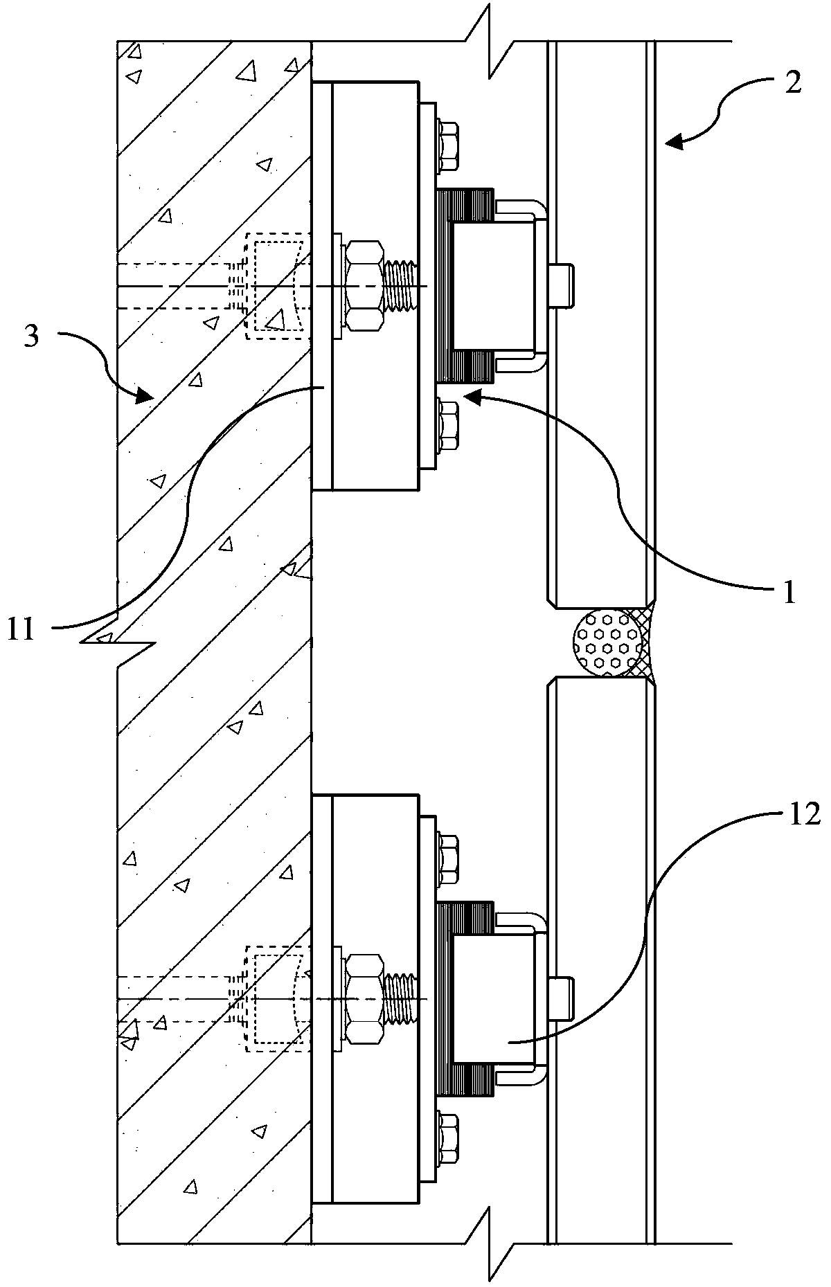
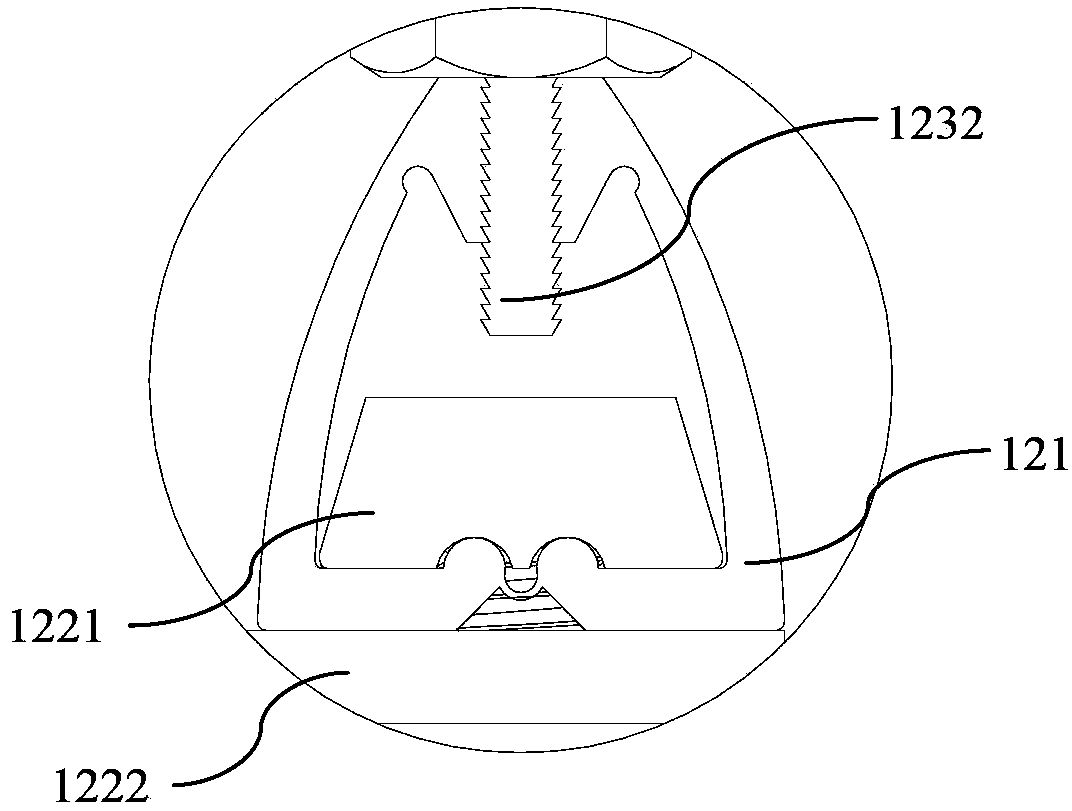
[0166] refer to Figure 1-Figure 5 As shown, in the first preferred embodiment of the present invention, the stone installation structure of the present invention includes a building body 3 and a stone 2 installed on the building body 3, and the installation structure also includes a plurality of mutually independent installation units 1, which are installed Unit 1 includes a pressing component 122, a fastening component 121 and a fastened component 123;

[0167] The fastened component 123 includes a bottom plate 1231 and a wing plate 1232 formed on the bottom plate 1231. The bottom plate 1231 is connected to the building body 3 through the building body connector 11, and the bottom plate 1231 is provided with a slot hole, and the fastened component 123 can pass through The groove-shaped hole on the bottom plate 1231 is adjusted along a first direction on the building body co...


PUM


Abstract

The invention discloses a stone installation structure, which comprises a building main body and stone installed on the building main body. The stone installation structure is characterized in that the installation structure also comprises a plurality of installation units mutually independent; the stone is adjusted to a setting position by the installation units and is fastened, and moreover, the position of the stone is not changed during a fastening process. As the stone installation structure disclosed by the invention is adopted, stimulation and control are provided for the dynamic generation process of the prestress of an elastic material to form a stable prestressed structure, and three-dimensional adjustment can be performed during an installation process, and therefore, the installation accuracy of the stone is greatly improved. The stone installation structure has the characteristics that the firmness, the accuracy and the safety degree are high and the convenience and the changeability are good.

Description

technical field [0001] The invention relates to a building material installation structure and an installation method, in particular to a dry-hanging stone installation structure and a stone installation method. Background technique [0002] Stone dry hanging is a construction process for building exterior walls. This process is to directly install facing stones on the exterior surface of building structures through connectors and bolts, leaving a certain space between stones and structures. Compared with the traditional wet work process, this process eliminates the grouting process, which can not only shorten the construction period, reduce the weight of the building, improve the seismic performance, but also effectively prevent the penetration and pollution of the stone by the saline and alkali pigments in the grouting, and improve the quality of the stone. Its appearance quality and decorative effect. [0003] In the current national standard "National Building Standard ...

Claims


Application Information

Patent Timeline
IPC IPC(8): E04F13/23
CPCE04F13/086E04F13/0853E04F13/144
Inventor 谢晓斌邹彤李震
Owner YIHE TECH DEV SHANGHAI
Learn More