


Quick Research
Generate reliable direction feasibility study reports for your R&D in just a few steps.

Technical Q&A
Discover and master advanced knowledge NOW. Basics, ideas, possibilities, all at once.

Find Solutions
As an expert in R&D theories, this can generate solutions to your technical problems instantly.

Evaluate Feasibility
Analyze your overall solution with one click, know your potential R&D risks in advance.

Monitor Landscape
Get weekly tech updates, stay abreast of the latest tech innovations and key insights.
Numerical control rotary table brake mechanism
A technology of numerical control turntable and brake mechanism, which is applied in the direction of metal processing machinery parts, large fixed members, metal processing equipment, etc., can solve the problems of wasting energy consumption and high manufacturing cost of brake parts, so as to reduce energy consumption, improve service life and reduce costs Effect
- Summary
- Abstract
- Description
- Claims
- Application Information
AI Technical Summary
Problems solved by technology
Method used
Image

Examples
Embodiment Construction
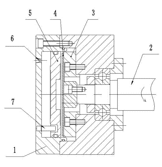
[0016] Such as figure 1 As shown, the present invention provides a numerical control turntable brake mechanism, including a brake cylinder 1 and a drive shaft 2, the front end of the drive shaft is installed in the brake cylinder, and the front end of the drive shaft is installed with a brake pad 4 through a bushing 3 , a piston 5 is installed in the brake cylinder, an air inlet 6 is arranged on the brake cylinder, and the brake pad and the piston are relatively installed.
[0017] A positioning pin 7 is arranged on the brake cylinder.
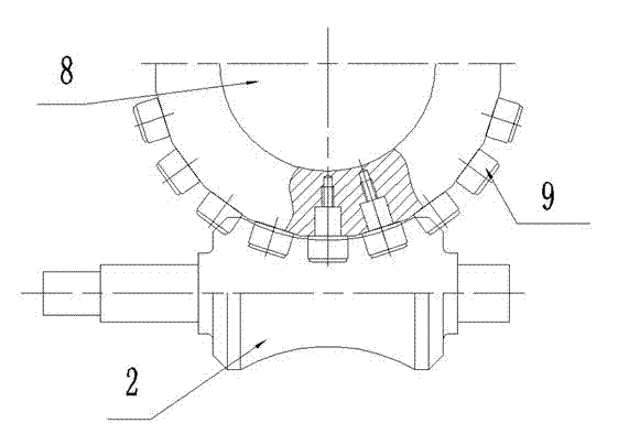
[0018] Such as figure 2 As shown, the numerically controlled turntable is a gapless numerically controlled turntable, including a worm gear 8 and a worm 2 that cooperate with each other, the drive shaft is a screw-shaped worm, and the worm gear is a turret structure in which needle roller driven bearings 9 are radially embedded. The turbine is in contact with the worm through the needle roller bearing, and there is no gap between the turbin...
PUM
 Abstract
Description
Claims
Application Information
 - R&D Engineer
- R&D Manager
- IP Professional
- Industry Leading Data Capabilities
- Powerful AI technology
- Patent DNA Extraction
Browse by: Latest US Patents, China's latest patents, Technical Efficacy Thesaurus, Application Domain, Technology Topic, Popular Technical Reports.
© 2024 PatSnap. All rights reserved.Legal|Privacy policy|Modern Slavery Act Transparency Statement|Sitemap|About US| Contact US: help@patsnap.com