Transmission self-locking device for rotary Z shaft of spray-painting device

A self-locking device, Z-axis technology, applied in the direction of the injection device, etc., can solve the problem of not easy to lock, and achieve the effect of reducing inertia and good self-locking function

Inactive Publication Date: 2013-10-16
邹力生
View PDF6 Cites 4 Cited by
  • Summary
  • Abstract
  • Description
  • Claims
  • Application Information

AI Technical Summary

Problems solved by technology

[0003] The purpose of the present invention is to solve the defect that the existing motor drives the Z beam up and down, but when the power of the motor is small, it is not easy to lock the defect, and to provide a transmission self-locking device for the Z axis of the painting device, so that the Z beam has a good locking function

Method used


Image

  • Transmission self-locking device for rotary Z shaft of spray-painting device

Examples


Embodiment Construction

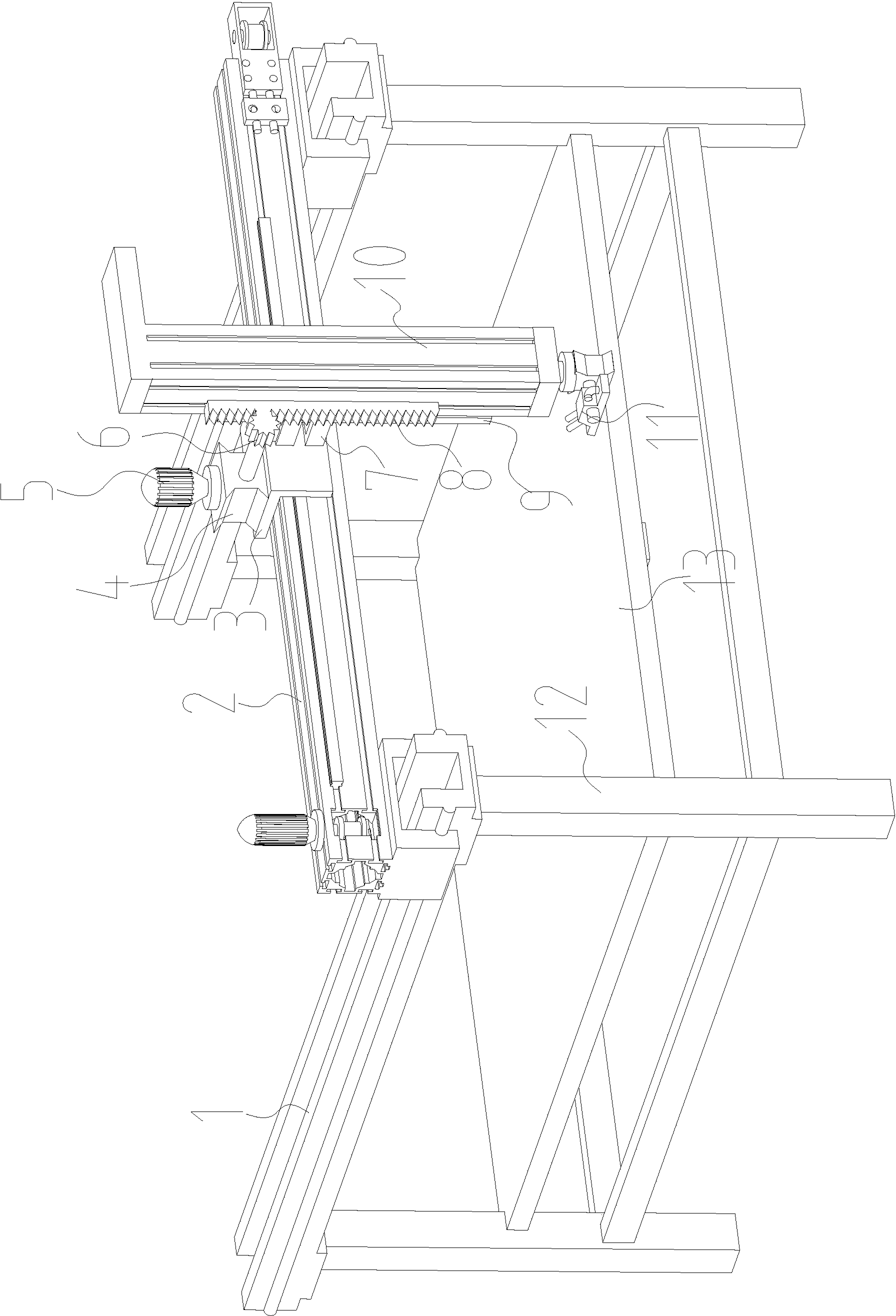
[0011] like figure 1 As shown, a transmission self-locking device for the Z-axis of a painting device includes a rectangular underframe 12, a horizontal bottom plate 13 is provided on the rectangular underframe 12, and a pair of X beams 1 are arranged on the rectangular underframe 12. Each X beam 1 is provided with a linear guide rail, and each guide rail is equipped with a slider, and a Y beam 2 is arranged on the two sliders, and each X beam 1 is also provided with a transmission belt, each One end of the transmission belt is connected with a corresponding slider, and the other end is matched with the pulley on the corresponding X-beam 1. The two pulleys are connected through a transmission shaft. A servo motor is arranged outside an X-beam and a corresponding Pulley connection, Y beam 2 is provided with a mobile frame 3 that can move along the Y direction, and the distance between the mobile frame 3 and Y beam 2 is also through linear guide rails and sliders, and one end...


PUM


Abstract

The invention relates to a transmission self-locking device for a rotary Z shaft of a spray-painting device. The transmission self-locking device comprises a rectangular base frame (12), wherein the rectangular base frame (12) is provided with a horizontal base plate (13); an X beam, a Y beam and a Z beam capable of moving relatively are arranged on the rectangular base frame. The transmission self-locking device is characterized in that one side of the Z beam (10) is provided with a linear guide rail (9); a moving rack (3) on the Y beam is provided with a linear bearing (7) matched with the linear guide rail (9); a worm and gear speed reducer (4) is also arranged on the moving rack (3); an input shaft is connected with a motor shaft of a motor (5); an output shaft is provided with a gear wheel (6); the other side of the Z beam (10) is provided with a gear rack (8) meshed with the gear wheel (10). The transmission self-locking device has the beneficial effect that the Z beam has a good self-locking function through the application of the worm and gear speed reducer, and the Z beam adopts aluminum extruded sections, so that the inertia generated when the Z beam moves can be reduced.

Description

technical field [0001] The invention relates to a woodworking painting device, in particular to a transmission self-locking device for the Z axis of the painting device. Background technique [0002] Existing carpentry painting device comprises a rectangular underframe, a horizontal bottom plate is arranged on the rectangular underframe, a pair of X-beams are arranged on the rectangular underframe, a linear guide rail is arranged on each X-beam, and each guide rail is equipped with One slider, two sliders are equipped with a Y beam, a mobile frame is provided on the Y beam, a Z beam can be lifted and lowered on the mobile frame, and a paint spraying head is installed at the lower end of the Z beam, so the whole Z beam is working In the state, it needs to bear the inertia generated by the movement, and it needs to be able to lock itself when it is lifted to the specified position during the lifting process. However, the existing motor-driven Z beam is generally used for l...

Claims


Application Information

Patent Timeline
Patent Type & Authority Applications(China)
IPC IPC(8): B05B15/10
Inventor 邹力生
Owner 邹力生
Why Eureka
Try Eureka