Laser regeneration amplifier

A regenerative amplifier and laser technology, applied in lasers, laser components, phonon exciters, etc., can solve problems affecting the stability of seed optical mode-locking, and achieve the effects of reducing self-focusing, efficient utilization, and high beam quality

Active Publication Date: 2013-10-09
11TH RES INST OF CHINA ELECTRONICS TECH GROUP CORP
View PDF5 Cites 3 Cited by
  • Summary
  • Abstract
  • Description
  • Claims
  • Application Information

AI Technical Summary

Problems solved by technology

[0005] It can be seen from the above that the seed light introduction and regeneration light export methods of the existing regenerative amplifiers have the problem that the regeneration light returns to the seed cavity, which affects the stability of the seed light mode-locking

Method used


Image

  • Laser regeneration amplifier
  • Laser regeneration amplifier

Examples


no. 1 example

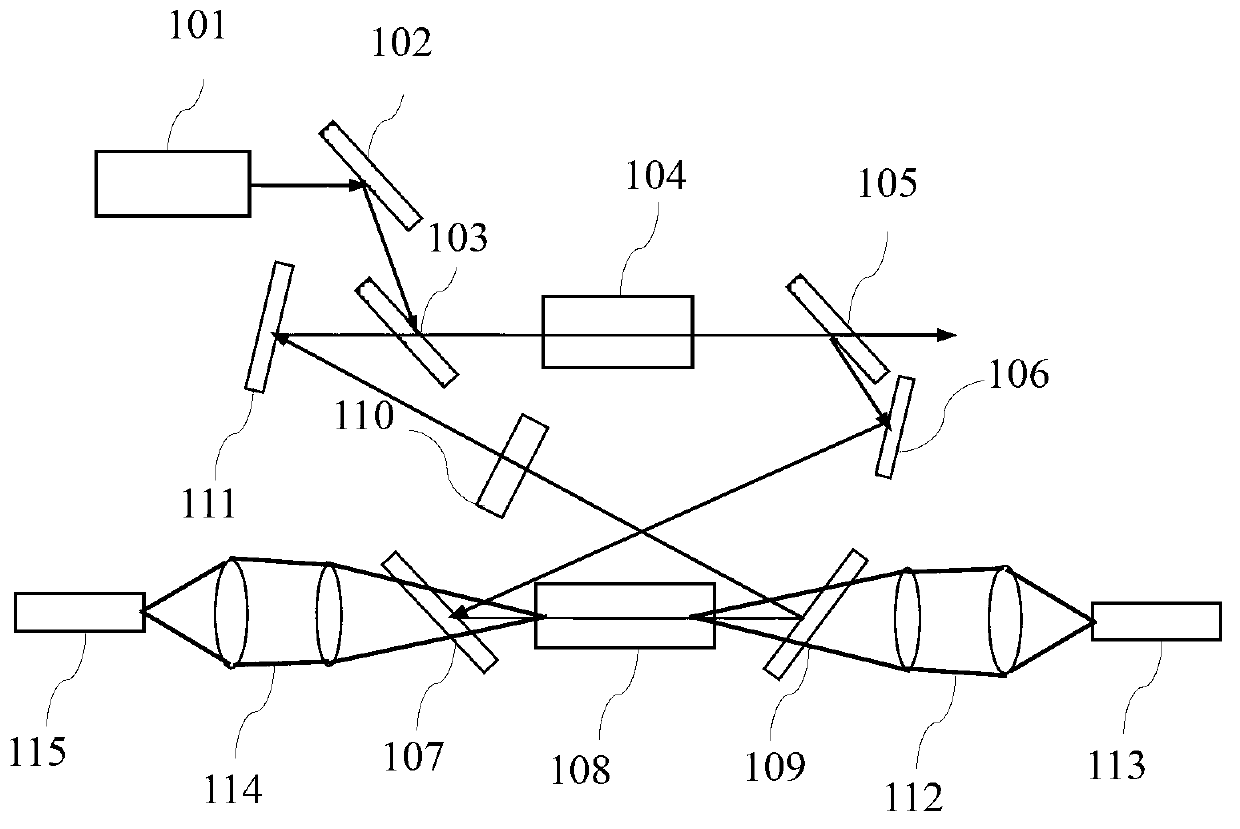
[0033] The first embodiment of the present invention, a laser regenerative amplifier, such as figure 1 As shown, it includes: an all-solid-state picosecond laser mode-locked oscillator 101, a first optical path adjustment module 102, an 8-shaped optical path resonator, a coupling module (112, 114) and a pumping module (113, 115), where the 8-shaped The optical path resonant cavity contains a Q-switched crystal 104 and a gain crystal 108 placed in parallel. The pump light emitted by the pump module (113, 115) is coupled into the gain crystal 108 through the coupling module (112, 114). The all-solid-state picosecond laser lock The seed light emitted by the mode oscillator 101 is adjusted by the first optical path adjustment module 102 and then enters the figure-of-eight resonant cavity.

[0034] All-solid-state picosecond laser mode-locked oscillator 101 is Nd:YVO 4 Mode-locked picosecond oscillator.

[0035] The first optical path adjustment module 102 is a polarizer or a Gla...


PUM


Abstract

The invention discloses a laser regeneration amplifier which comprises an all-solid picosecond laser mode locking oscillator, a first light path adjusting module, a curve-eight-shaped light path resonant cavity, a coupling module and a pumping module, wherein the curve-eight-shaped light path resonant cavity comprises a Q-switching crystal and a gain crystal which are placed in parallel, pumping light emitted by the pumping module enters the gain crystal through coupling of the coupling module, and seed light emitted by the all-solid picosecond laser mode locking oscillator passes through the first light path adjusting module for light path adjusting, then enters the curve-eight-shaped light path resonant cavity, is amplified for multiple times in the gain crystal and then is output through the Q-switching crystal. According to the technical scheme, regeneration amplified light can not return along the transmission light path of the seed light, and the influence on the seed light by the regeneration amplified light is effectively eliminated.

Description

technical field [0001] The invention relates to the technical field of laser amplification, in particular to a laser regenerative amplifier. Background technique [0002] The high repetition rate optical pulses generated by the mode-locked laser have an extremely narrow pulse width, usually 10 -10 ~10 -15 seconds, has attracted widespread attention, but its single pulse energy is on the order of nanojoules and its peak power is low, which greatly limits its application in some fields. [0003] In order to obtain higher peak power and greater single-pulse energy, it is necessary to perform optical amplification on the seed light, and the commonly used amplification methods include single-pass, multi-pass and regenerative amplification. The single-pass method only passes through the gain medium once, and the extracted energy is low; although the multi-pass method can extract energy multiple times, it cannot guarantee that the seed light and the pump light can be effectively ...

Claims


Application Information

Patent Timeline
Patent Type & Authority Applications(China)
IPC IPC(8): H01S3/086H01S3/115
Inventor 毛小洁秘国江庞庆生邹跃
Owner 11TH RES INST OF CHINA ELECTRONICS TECH GROUP CORP
Why Eureka
Try Eureka