


Quick Research
Generate reliable direction feasibility study reports for your R&D in just a few steps.

Technical Q&A
Discover and master advanced knowledge NOW. Basics, ideas, possibilities, all at once.

Find Solutions
As an expert in R&D theories, this can generate solutions to your technical problems instantly.

Evaluate Feasibility
Analyze your overall solution with one click, know your potential R&D risks in advance.

Monitor Landscape
Get weekly tech updates, stay abreast of the latest tech innovations and key insights.
Coriolis mass flow meter
A technology of mass flowmeter and Coriolis, which is applied in the direction of direct mass flowmeter, mass flow measurement device, measurement flow/mass flow, etc., and can solve problems such as difficulty in accurate measurement
- Summary
- Abstract
- Description
- Claims
- Application Information
AI Technical Summary
Problems solved by technology
Method used
Image

Examples
Embodiment Construction
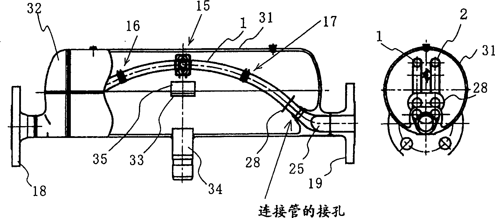
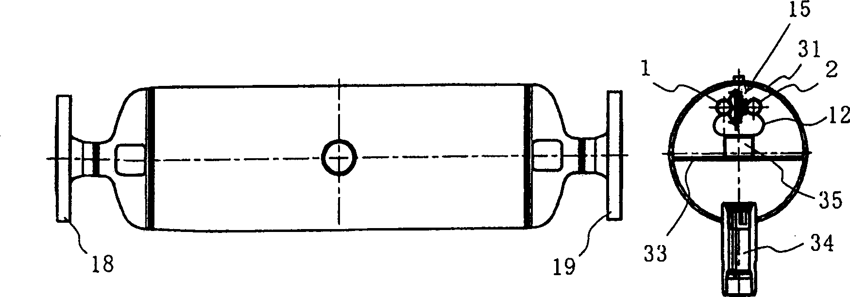
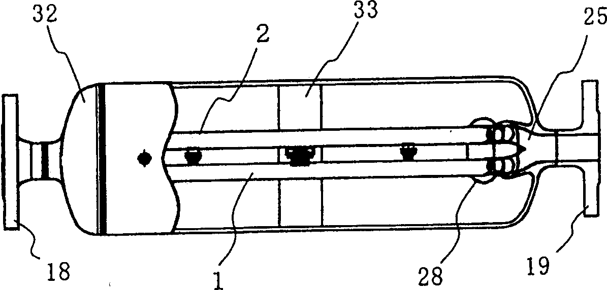
[0023] Figures 1 to 4 A first embodiment of the arcuate tube type Coriolis mass flowmeter of the present invention employing two parallel arcuate flow tubes is described. The Coriolis mass flowmeter shown can be used in either a vertical or horizontal orientation, and when used in a horizontal orientation, the raised portion in the middle of the flow tube can be positioned either up or down. It should be noted, however, that when used to measure gases, the raised portion of the flow tube is preferably positioned upward, as shown, to prevent liquid from becoming lodged in the raised portion, and when used to measure liquids, the raised portion Position the part downwards to prevent air bubbles from becoming trapped there.
[0024] Figures 1 to 4 Shown is a Coriolis mass flow meter of the present invention; figure 1 It is a partially sectioned front view (as shown on the left) and a side view cut at the main pipe (as shown on the right) when the inlet and outlet pipes are i...
PUM
 Abstract
Description
Claims
Application Information
 - R&D Engineer
- R&D Manager
- IP Professional
- Industry Leading Data Capabilities
- Powerful AI technology
- Patent DNA Extraction
Browse by: Latest US Patents, China's latest patents, Technical Efficacy Thesaurus, Application Domain, Technology Topic, Popular Technical Reports.
© 2024 PatSnap. All rights reserved.Legal|Privacy policy|Modern Slavery Act Transparency Statement|Sitemap|About US| Contact US: help@patsnap.com