
A power control circuit and method for stabilizing a power supply

A technology of power control and power controller, which is applied in active power filtering, circuit devices, AC network circuits, etc., and can solve problems such as deteriorating power quality of power supplies

Active Publication Date: 2013-10-02
VERSITECH LTD
View PDF3 Cites 15 Cited by
  • Summary
  • Abstract
  • Description
  • Claims
  • Application Information

AI Technical Summary

Problems solved by technology

To improve power quality, they are installed in high current applications such as welding equipment, causing large and non-linear currents, deteriorating the power quality of the power supply

Method used


Image

  • A power control circuit and method for stabilizing a power supply
  • A power control circuit and method for stabilizing a power supply
  • A power control circuit and method for stabilizing a power supply

Examples


Embodiment Construction

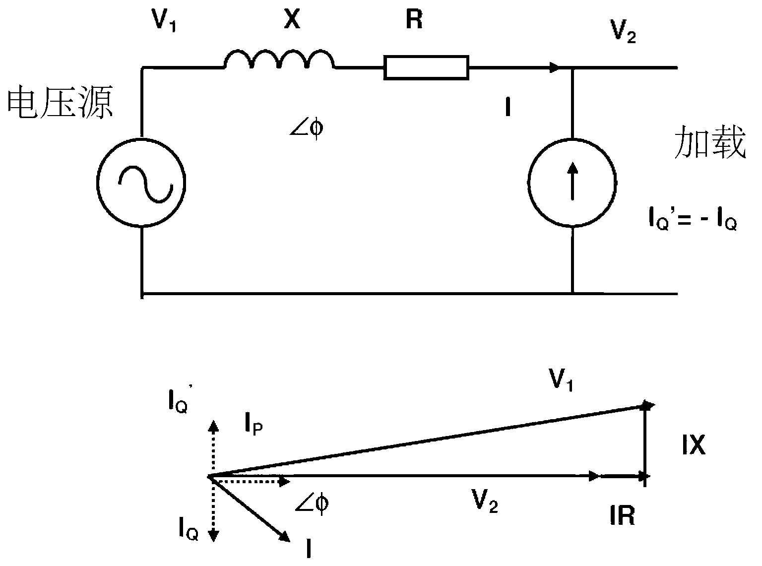
[0085] With reference to the accompanying drawings, it is shown that a power control circuit 1 can be connected to a load 2 for receiving a power source 3 . The power control circuit 1 is adapted to absorb power from the power source 3 and to output power to the power source to stabilize at least one electrical parameter of the power source 3 . The power absorbed and output by the power control circuit 1 includes reactive power, active power, or both.

[0086] In some embodiments, the power control circuit 1 is further adapted to output power to the load 2 to stabilize at least one electrical parameter of the power source 3 .

[0087] Also in some embodiments, the at least one electrical parameter is a voltage, and the power control circuit 1 keeps the power supply 3 at the rated power supply voltage V s . The rated mains voltage may be any rated mains voltage provided by different national grids. For example, the nominal mains voltage may be 110V, 220V, 230V, or 240V. In ...


PUM


Abstract

A power control circuit connectable to a load adapted to receive a power supply and a method of stabilizing at least one electrical parameter of the power supply connectable to the load. The power control circuit is adapted to absorb power from the power supply and adapted to deliver power to the power supply to stabilize at least one electrical parameter of the power supply. The method includes the following steps: absorbing power from the power supply or delivering the power to the power supply. At least one electrical parameter of the power supply includes parameters such as voltage and frequency.

Description

technical field [0001] The present invention relates to power control circuits and methods for stabilizing power sources, in particular, but not limited to, such circuits and methods for use with distributed loads connected to dynamically changing power sources, such as those generated by dynamically changing renewable energy sources Dynamically changing power supply. Background technique [0002] The growing need to develop renewable energy sources, such as wind, solar, geothermal, and ocean wave energy, has raised new concerns about the uncertainty of future grids. In traditional power systems the amount and rate of power generation is strictly controlled by power plants. In emerging grids, also known as smart grids, more and more stand-alone and distributed renewable energy from small-scale rooftop solar panels to large-scale wind farms will be installed on the grid with or without central planning. different parts. For such a dynamically changing smart grid, it will b...

Claims


Application Information

Patent Timeline
Patent Type & Authority Applications(China)
IPC IPC(8): H02J3/00H02J3/12H02J3/14H02J3/16H02J3/18H02J3/24
CPCH02J3/1814Y02E40/30H02J3/1842H02J3/18H02J3/12Y02E40/10Y02E40/20H02J3/241H02J3/16
Inventor 许树源李志群吴复立
Owner VERSITECH LTD
Learn More