
Component inserter with overhead horizontal slide rails

A horizontal slide rail, top-mounted technology, applied in the direction of electrical components, electrical components, etc., can solve the problems of inconsistent PCB board size, troublesome plug-in machine equipment manufacturing, affecting the plug-in head mechanism and plug-in action, etc., to reduce production. Cost, simplified assembly, high functionality

Active Publication Date: 2013-10-02
DONGGUAN SUMIDA AUTOMATION CO LTD
View PDF5 Cites 2 Cited by
  • Summary
  • Abstract
  • Description
  • Claims
  • Application Information

AI Technical Summary

Problems solved by technology

[0003] The existing plug-in head mechanism (that is, the clamping device) is set on the frame, and the relative movement between the clamping device and the PCB board is realized by moving the PCB board, but the size of the PCB board is not consistent in actual production and processing, so it is necessary to The dimensions and specifications of the PCB fixture are often replaced or changed, and at the same time, it is necessary to ensure that the board-feeding guide rails that transport the PCB board can move accurately horizontally, which brings a lot of trouble to the manufacture of the plug-in machine equipment.
In addition, the plug-in head mechanism (that is, the clamping device) and the plate-feeding guide rail are located at the same position of the rack, so that the movement range of the plug-in head mechanism in the horizontal position is limited, and the moving parts of the plate-feeding guide rail and the plug-in head The moving parts of the mechanism interfere with each other, which seriously affects the retrieving and plug-in action of the plug-in head mechanism, and at the same time increases the difficulty of assembling the plug-in machine equipment, and the defects are obvious

Method used


Image

  • Component inserter with overhead horizontal slide rails
  • Component inserter with overhead horizontal slide rails
  • Component inserter with overhead horizontal slide rails

Examples


Embodiment Construction

[0023] In order to facilitate the understanding of those skilled in the art, the present invention will be further described below in conjunction with the embodiments and accompanying drawings, and the contents mentioned in the embodiments are not intended to limit the present invention.

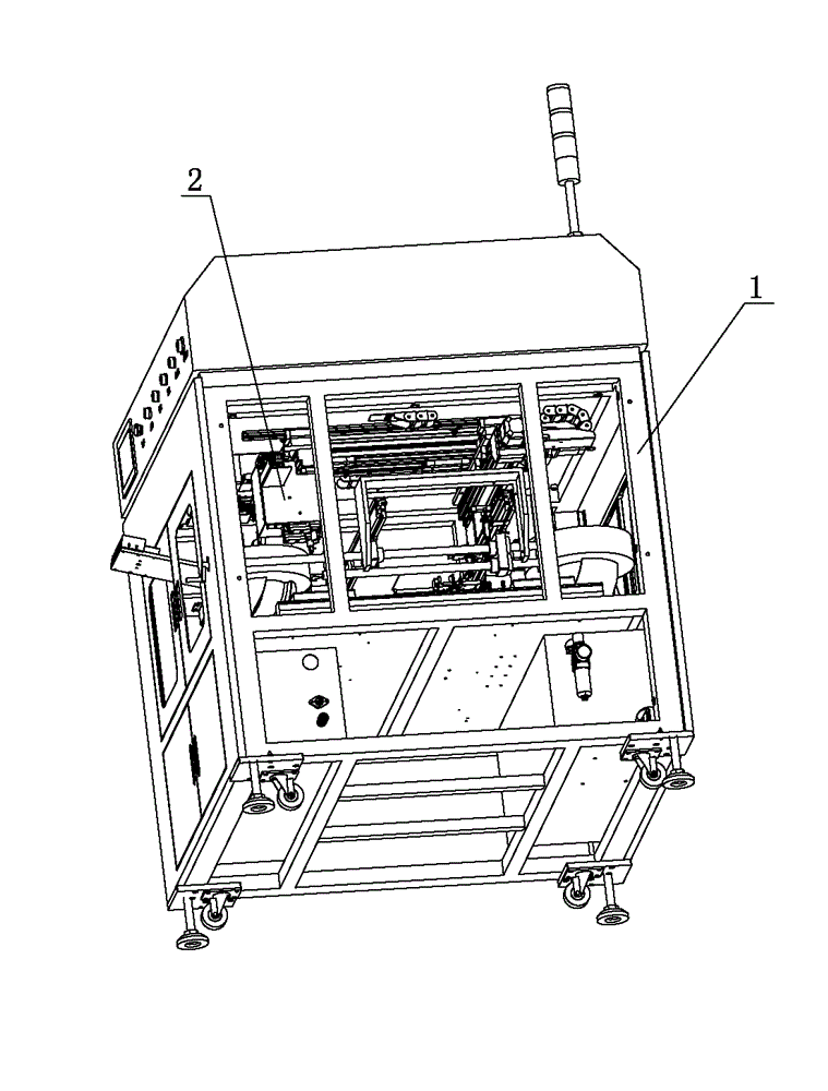
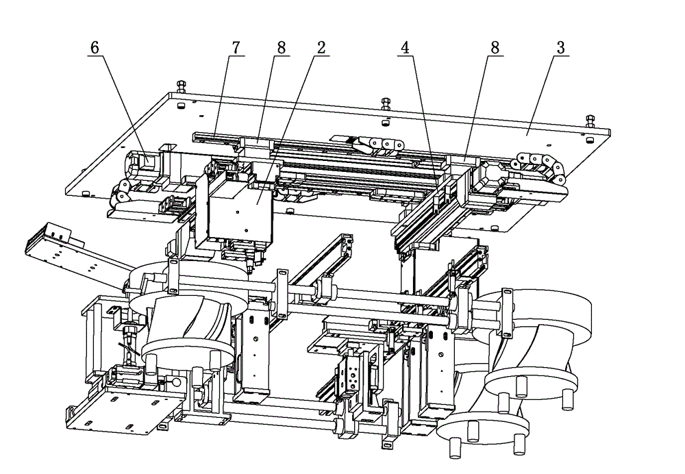
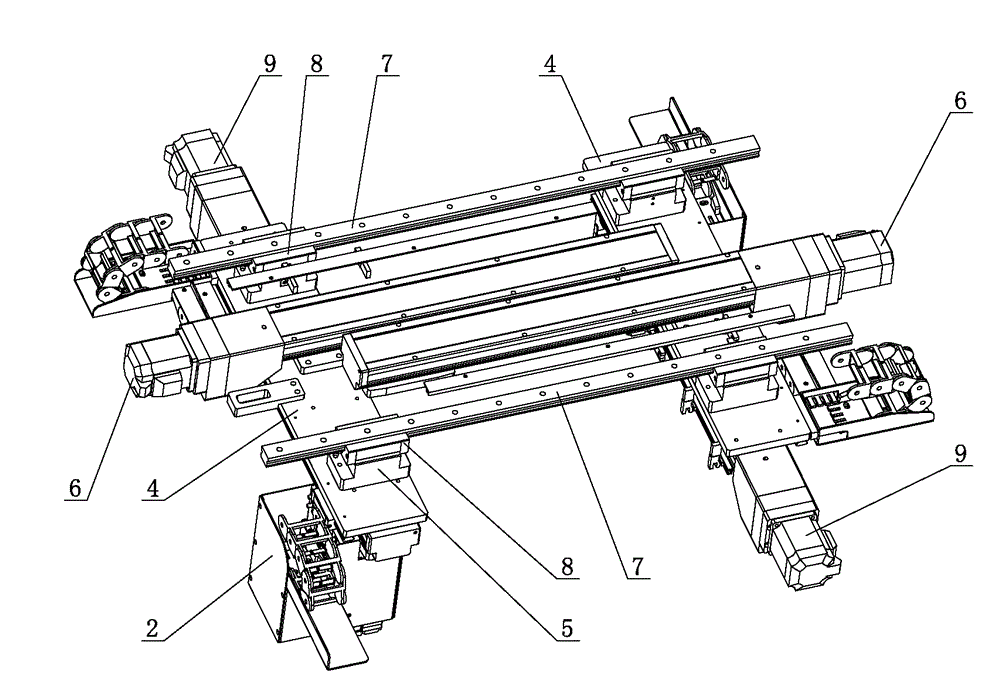
[0024] Such as Figure 1 to Figure 8 As shown, a top-mounted plug-in machine with horizontal slide rails includes a frame 1 and a plug-in head mechanism 2. The frame 1 is provided with a board-feeding guide rail for transporting PCB boards. The top of the frame 1 is fixed with a substrate 3 The lower side of the base plate 3 is equipped with a horizontally movable long plate base 4 and a horizontal drive mechanism for driving the long plate base 4 to move back and forth horizontally, and the lower side of the long plate base 4 is equipped with a vertically movable machine head Base 5 and the vertical drive mechanism that drives the head base 5 to move back and forth longitudinally.

[0025]...


PUM


Abstract

The invention relates to the technical field of PCB (printed circuit board) assembling and processing equipment, in particular to a component inserter with overhead horizontal slide rails, which comprises a frame and component inserting head mechanisms, wherein a baseplate is fixedly mounted at the top of the frame; long plate bases and transverse driving mechanisms are mounted on the lower side of the baseplate; machine head bases and longitudinal driving mechanisms are mounted on the lower sides of the long plate bases; the component inserting head mechanisms are mounted on the lower sides of the machine head bases; plate conveying guide rails are positioned under the component inserting head mechanisms. As a horizontal moving mechanism for driving the component inserting head mechanisms to move is positioned on the lower side of the baseplate, and the baseplate is positioned above the plate conveying guide rails and completely separated from the plate conveying guide rails, the component inserting head mechanisms are enabled to move freely above the plate conveying guide rails without space limitation, the problem of mutual interference between the moving components of the plate conveying guide rails and the moving components of the component inserting head mechanisms is completely avoided, the component inserting head mechanisms can take materials beyond the airspace range of the plate conveying guide rails, and high practicability is achieved.

Description

technical field [0001] The invention relates to the technical field of PCB assembly and processing equipment, in particular to a top-mounted plug-in machine with horizontal slide rails. Background technique [0002] With the rapid development of electronic technology, the use of electronic products is becoming more and more extensive. PCB circuit boards are important equipment for electronic products, and plug-in machines are processing equipment that insert various electronic components into designated positions on PCB circuit boards. During the processing of the plug-in machine, the electronic components are generally transported to the top of the PCB board by the clamping device for positioning, and then the clamping device moves down to accurately insert the electronic components into the preset pins of the PCB circuit board. In the hole, then the clamping device resets to facilitate the clamping of new electronic components for the next plug-in processing. The inserted ...

Claims


Application Information

Patent Timeline
IPC IPC(8): H05K13/04
Inventor 余景亮
Owner DONGGUAN SUMIDA AUTOMATION CO LTD
Learn More