
Solenoid valve fault diagnostic method based on current detection

A fault diagnosis and current detection technology, applied in the direction of measuring electricity, measuring devices, measuring electrical variables, etc., can solve the problems of changing the rigidity of the hydraulic system and not having intelligent identification

Active Publication Date: 2013-10-02
PLA SECOND ARTILLERY ENGINEERING UNIVERSITY
View PDF3 Cites 36 Cited by
  • Summary
  • Abstract
  • Description
  • Claims
  • Application Information

AI Technical Summary

Problems solved by technology

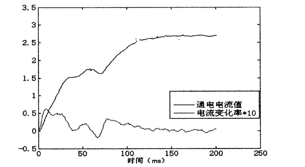
Among them, Professor Wu Genmao of Zhejiang University and student Li Weibo analyzed the normal current of the solenoid valve and the stuck current of the spool, but only used the inflection point of the current curve to analyze intuitively, but did not carry out intelligent identification of the two states; Harbin Institute of Technology Professor Zhang Donglai and Ma Xin from Shanghai Institute of Aerospace Control Engineering conducted research on the slow-change failure process of solenoid valves, but did not analyze specific faults; Professor Cai Wei from the Second Artillery Engineering University and his students Xiao Yongchao and Zhou Jie used magnetic field sensors and The acceleration sensor detects the magnetic field signal and vibration signal, but does not analyze the current signal; Xie Fang from the University of Electronic Science and Technology of China and Hao Shengqiao from Shanghai Jiaotong University respectively detect the pressure and flow changes at the inlet and outlet of the hydraulic valve, which changes the rigidity of the hydraulic system.

Method used


Image

  • Solenoid valve fault diagnostic method based on current detection
  • Solenoid valve fault diagnostic method based on current detection
  • Solenoid valve fault diagnostic method based on current detection

Examples


specific Embodiment approach

[0031] Now in conjunction with accompanying drawing, the specific embodiment of the present invention is set forth as follows:

Embodiment

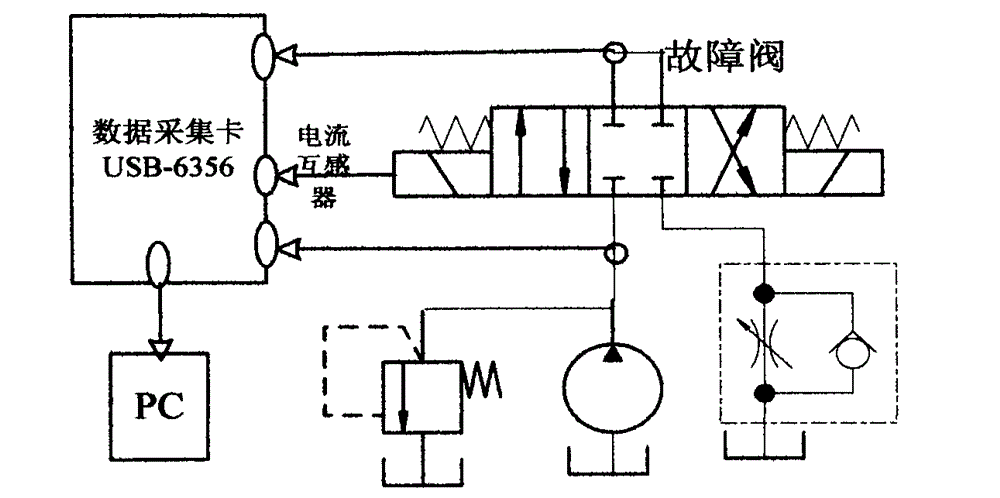
[0033] Step 1: Set the faults of spool stuck, spring broken and spool unable to reset

[0034] Step 1.1: The spring at one end of the solenoid valve is broken. The method is to take out the spring between the plunger and the valve core at one end of the solenoid valve. When the electromagnetic coil at the other end is energized, the direction can be reversed reliably, but when it is disconnected, due to the lack of spring force for the spool to restore the neutral function, the spool is still in the working position, so the energized state simulates the fault when the spring breaks, and in the working position Power on can simulate the fault that the spool cannot be reset normally;

[0035] Step 1.2: One end of the solenoid valve is completely stuck. The method is to take out the spring between the ejector rod at one end of the solenoid valve and the valve core, and replace it with multiple pieces of hard paper. When the coil is energized, the solenoid valve is still in the...


PUM


Abstract

The invention relates to a solenoid valve fault diagnostic method, especially relates to a fault diagnostic method which is based on a current detection method and uses three-layer wavelet energy decomposition extraction characteristic values and a BP neural network for mode identification. The solenoid valve fault diagnostic method is characterized in that based on characteristics of current step signals, an electricity quantity isolation sensor is connected in series at a solenoid valve drive end for performing three-layer wavelet decomposition on a current change rate; relative energy values are extracted as eigenvectors; then the BP neutral network is used for classifying four kinds of signals, namely normal valve signals, valve core clamp stagnation valve signals, spring fracture valve signals and valve core resetting failure valve signals, and is used for accurately determining relative states of the solenoid valve, including valve core clamp stagnation, spring fracture and valve core resetting failure. Compared with similar products in the prior art, the solenoid valve fault diagnostic method based on current detection has the advantages of easy extraction of signals, high accuracy, low cost and the like.

Description

Technical field: [0001] The invention belongs to the technical field of hydraulic system fault diagnosis, and relates to a fault diagnosis method for an electromagnetic reversing valve, in particular to a fault diagnosis based on a current detection method, which adopts three-layer wavelet energy decomposition to extract eigenvalues ​​and BP neural network for pattern recognition method. Background technique: [0002] As a key component of the hydraulic system, the solenoid valve's performance and safety will directly affect the efficiency, safety and reliability of the entire hydraulic system. In order to ensure the safe and reliable operation of hydraulic equipment, the research on fault diagnosis of hydraulic equipment is becoming more and more active. With the improvement of the degree of automation, fault diagnosis has changed from the use of simple instruments and personal sense and practical experience to the stage of sensor and intelligent diagnosis. Among them, pr...

Claims


Application Information

Patent Timeline
IPC IPC(8): G01R31/00G01M13/00
Inventor 高钦和李向阳张志利龙勇
Owner PLA SECOND ARTILLERY ENGINEERING UNIVERSITY
Learn More