Modularized fiber-optic gyroscopic compass

A fiber optic gyroscope and compass technology, which is applied in the field of fiber optic gyroscope north-finding devices, can solve the problems of fast north-seeking speed, long time for north-finding devices, and low cost, and achieve lower accuracy requirements, improved north-finding accuracy, and easy adjustment flat effect

Active Publication Date: 2013-10-02
HUBEI SANJIANG AEROSPACE HONGFENG CONTROL
View PDF6 Cites 9 Cited by
  • Summary
  • Abstract
  • Description
  • Claims
  • Application Information

AI Technical Summary

Problems solved by technology

[0005] In view of the above defects or improvement needs of the prior art, the present invention provides a fiber optic gyro compass, the purpose of which is to selectively configure fiber optic gyroscopes and quartz accelerometers in three measurement directions in space by adopting a modular configuration method and correspondingly provide The corresponding measurement method has the advantages of low cost and fast north-seeking speed, and reduces the accuracy requirements for fiber optic gyroscopes and quartz accelerometers, thereby solving the problem of long north-seeking time of current north-finding instruments and the obtained space gravity acceleration and space angular velocity It is not comprehensive and cannot be taken into account at the same time, and its north-finding accuracy is greatly improved

Method used


Image

  • Modularized fiber-optic gyroscopic compass
  • Modularized fiber-optic gyroscopic compass
  • Modularized fiber-optic gyroscopic compass

Examples


Embodiment 1

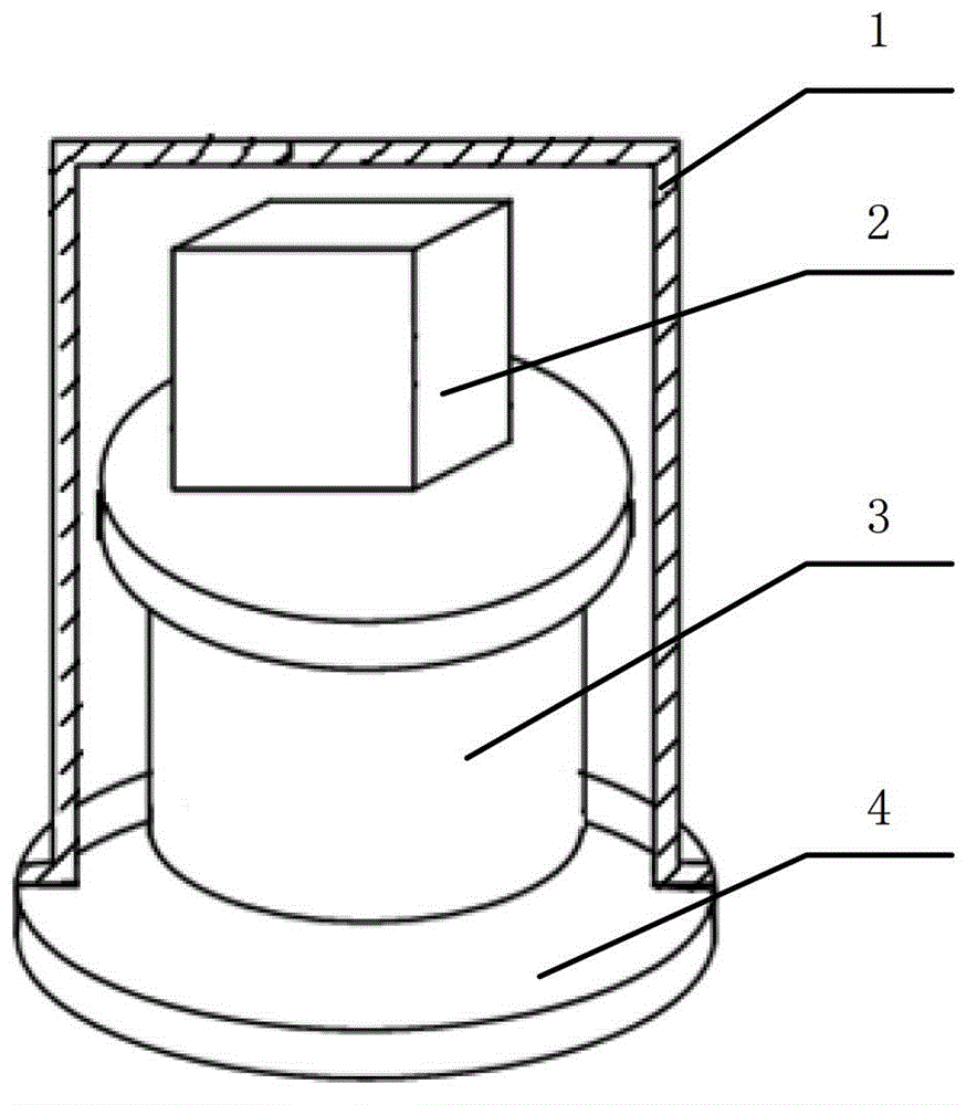
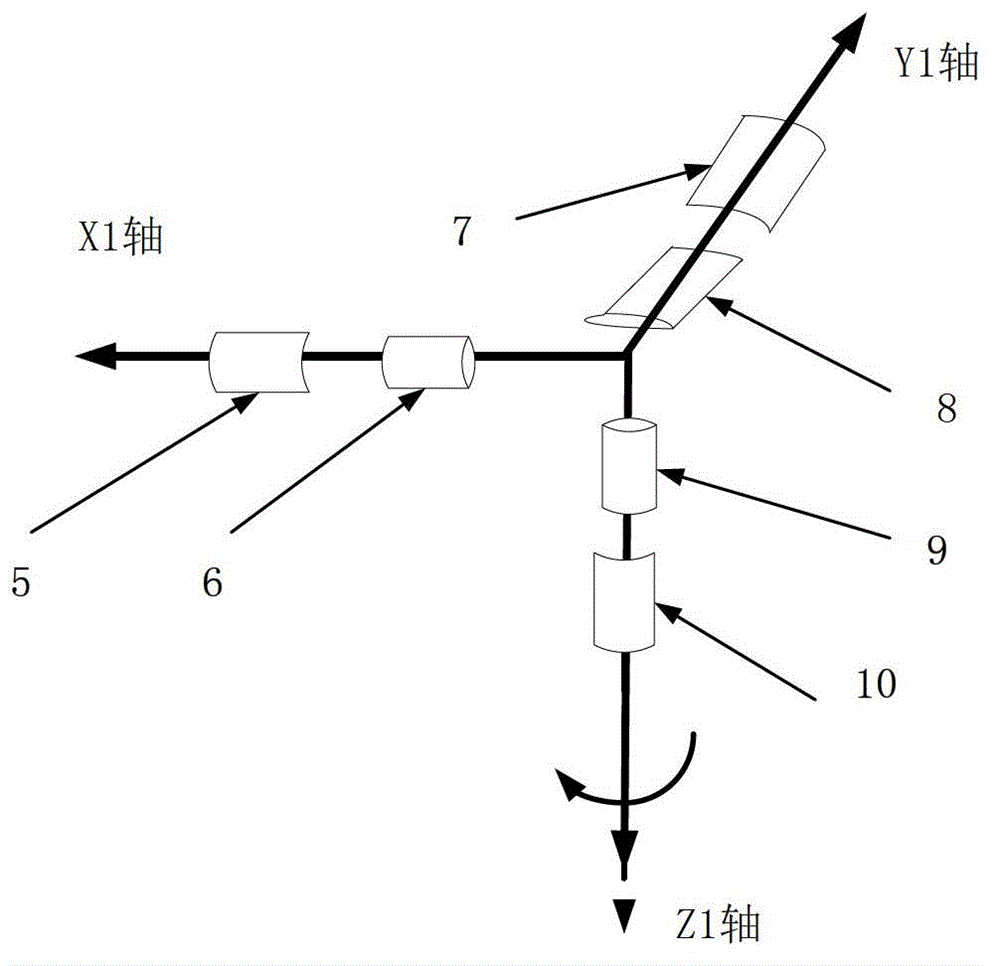
[0034] Such as figure 2 As shown in , there are three fiber optic gyroscopes and accelerometers in this embodiment, and one fiber optic gyroscope and accelerometer is arranged on each coordinate axis orientation of the space coordinate system. Specifically, fiber optic gyroscopes 5 , 7 , and 9 and quartz accelerometers 6 , 8 , and 10 are respectively installed on the three coordinate axes X1 , Y1 , and Z1 of the space coordinate system. In this configuration mode, it can be sensitive to the angular velocity and acceleration signals of the X1, Y1, and Z1 axes, that is, it can be sensitive to the angular velocity and acceleration information of the 3-dimensional space in real time.

[0035] When starting to work, the indexing control mechanism 3 returns to the zero position and locks at the 0° position, and the inertial group 2 collects data for a certain period of time, such as 1min to 8min; after that, the indexing control mechanism turns to the 180° position and locks, and t...

Embodiment 2

[0037]In this embodiment, there are two fiber optic gyroscopes, which are respectively arranged on two directions perpendicular to the rotation axis of the three coordinate axis directions of the space coordinate system, and three accelerometers, which are respectively arranged at the directions of each coordinate axis of the space coordinate system superior. Specifically, two fiber optic gyroscopes 5, 7 are installed on the coordinate axes X1, Y1 of the space coordinate system, and three quartz accelerometers 6, 8, 10 are installed on the X1, Y1, Z1 axes. In this configuration mode, it can be sensitive to the angular velocity signals on the X1 and Y1 axes, and the acceleration signals on the X1, Y1, and Z1 axes, that is, it can be sensitive to the angular velocity information in the rotation plane and the acceleration information in the 3-dimensional space in real time.

[0038] When working, the compass first remains in a static state, and then the indexing control mechanism...

Embodiment 3

[0040] In this embodiment, there is one fiber optic gyroscope, which is set on any coordinate axis orientation perpendicular to the rotation axis. on the coordinate axis. Specifically, an optical fiber gyroscope 5 is installed on the X1 axis, and a quartz accelerometer 6 and 10 are respectively installed on the X1 axis and the Z1 axis. Of course, the fiber optic gyroscope can also be installed on other axes, and the corresponding accelerometer can also be installed on other coordinate axis orientations. In this configuration mode, the angular velocity signal on the X1 axis and the acceleration signal on the X1 and Z1 axes can be sensitive.

[0041] When working, the compass first remains in a static state, and then the indexing control mechanism returns to the zero position and locks at the 0° position. The inertial group 2 is still for data collection, and the time can be, for example, 1 minute. Then the indexing control mechanism is forwarded to the 90° position and locked...


PUM


Abstract

The invention discloses a fiber-optic gyroscopic compass. The fiber-optic gyroscopic compass comprises a shell, an inertia set, a rotary position control mechanism and a base, wherein the inertia set, the rotary position control mechanism and the base are contained in the shell; the rotary position control mechanism is arranged on the base; the inertia set is arranged on a rotary tray of the rotary position control mechanism and comprises at least one fiber-optic gyroscope for sensing an outer angle accelerated speed and at least two accelerometers for sensing an accelerated speed; no more than one fiber-optic gyroscope is arranged in each coordinate axis direction of three coordinate axis directions of a space coordinate system and no more than one accelerometer is arranged in each coordinate axis direction; the inertia set is controlled by the rotary position control mechanism to rotate between each two measurement directions and is locked for data acquisition after rotating in place; then, a measured result is obtained after resolving. According to the compass disclosed by the invention, the precision requirements on the fiber-optic gyroscopes and the quartz accelerometers are reduced, the problems that north-seeking time of a current north-seeking instrument is long and that obtained space gravitational acceleration and space angle speeds are not comprehensive and cannot be taken into account are solved, and the north-seeking precision is greatly improved.

Description

technical field [0001] The invention belongs to the field of fiber optic gyro north finders, and in particular relates to a fiber optic gyro compass. Background technique [0002] The fiber optic gyro compass is a kind of gyro north finder, but unlike the pendulum gyro compass, it has no complicated frame and leveling mechanism, so it is not only low in cost, but also has strong adaptability. The fiber optic gyro compass can output the north-seeking azimuth of the geographical location in a static environment, and can also dynamically output the real-time changing attitude angle of the carrier. [0003] At present, the commonly used fiber optic gyro compass is generally a solid compass, and three fiber optic gyroscopes and three quartz accelerometers are respectively installed on the X, Y and Z coordinate axes in space. North precision, which has high requirements on the accuracy of fiber optic gyroscopes and quartz accelerometers, and the installation requirements of fiber...

Claims


Application Information

Patent Timeline
Patent Type & Authority Applications(China)
IPC IPC(8): G01C19/72
Inventor 王爱民李亮王勇刚杨双俊王红平
Owner HUBEI SANJIANG AEROSPACE HONGFENG CONTROL
Why Eureka
Try Eureka