
Compound type cooling system for engine and vehicle using same

A cooling system and engine technology, applied in the direction of engine cooling, engine components, machines/engines, etc., can solve problems such as the engine cannot dissipate heat normally, and achieve the effect of saving energy

Inactive Publication Date: 2013-10-02
LONGKOU ZHONGYU THERMAL MANAGEMENT SYST SCIAND TECH
View PDF7 Cites 8 Cited by
  • Summary
  • Abstract
  • Description
  • Claims
  • Application Information

AI Technical Summary

Problems solved by technology

[0005] The technical problem to be solved by the present invention is to provide a compound cooling system for the engine, which can effectively overcome the problem that the engine cannot dissipate heat normally due to the failure of the generator, improve the utilization rate of electric energy, and make the space arrangement of the system more flexible. When the temperature is high, the cooling fan can be adjusted in time according to the needs. The invention also provides a vehicle using the composite cooling system.

Method used


Image

  • Compound type cooling system for engine and vehicle using same
  • Compound type cooling system for engine and vehicle using same
  • Compound type cooling system for engine and vehicle using same

Examples


Embodiment 1

[0021] Such as figure 1 As shown, the compound cooling system for the engine in this embodiment includes a radiator for providing coolant for the engine, a circulation line 11 for delivering the coolant, an intercooler for cooling the output gas of the engine supercharger, and Pipeline 12 for conveying gas. An electronically controlled clutch fan 13 is arranged at the radiator to cool down the coolant in the radiator. The electronically controlled clutch fan 13 adopts a clutch with multi-stage speed change. The power of the electronically controlled clutch fan is provided by the engine of the vehicle. A water temperature sensor 14 is provided on the pipeline section for delivering the coolant heated by the engine to the radiator. A motor fan 15 is arranged at the intercooler to cool down the high-temperature gas in the intercooler. The power of the motor fan is provided by the battery of the vehicle, and the gas delivery pipeline 12 is a pipe for delivering high-temperature g...

Embodiment 2

[0024] Such as figure 2 As shown, the difference between this embodiment and the first embodiment is that the water temperature sensor 24 is arranged on the pipeline section that delivers coolant from the radiator to the engine, and the air temperature sensor 26 is installed on the pipeline section that delivers low-temperature gas from the intercooler to the engine. .

[0025] The overall control method of the cooling system is the same, only that the action value of the logic controller setting stage needs to be adjusted accordingly.

Embodiment 3

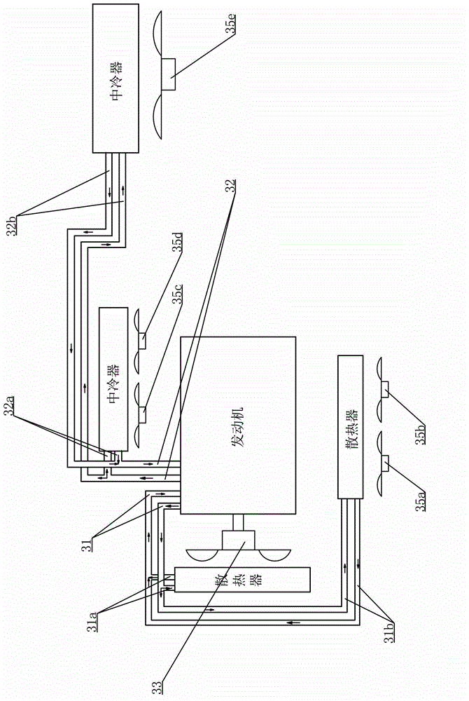
[0027] Such as image 3 As shown, the difference between this embodiment and Embodiments 1 and 2 is that there are two radiators that provide coolant for the engine, and the branch circulation pipelines 31a, 31b of the two radiators that deliver coolant are connected in parallel to deliver coolant to the engine. The circulation pipeline 31 of the coolant communicates, and an electronically controlled clutch fan 33 is arranged at one of the radiators, and an electric fan 35a, 35b is arranged at the other radiator, and the intercooler that provides cooling for the output gas of the engine supercharger is provided with two One, the branch pipes 32a, 32b for conveying gas of the two intercoolers are connected together to communicate with the pipeline 32 for conveying gas to the engine, and electric fans 35c, 35d, 35e are respectively arranged at the two intercoolers.


PUM


Abstract

The invention relates to a compound type cooling system for an engine. The compound type cooling system for the engine comprises a radiator, a circulation pipeline, an intercooler and a pipeline, wherein the radiator is used for providing refrigerants for the engine, the circulation pipeline is used for conveying the refrigerants for the engine, the intercooler is used for cooling gas output by an engine supercharger, the pipeline is used for conveying gas for the engine, an electronic control clutch fan is arranged on the radiator, a water temperature sensor is arranged on the circulation pipeline used for conveying the refrigerants, an electromotor fan is arranged on the intercooler, and a gas temperature sensor is arranged on the pipeline used for conveying the gas. The compound type cooling system is adjusted and is controlled by a logic controller, and a control circuit of the electronic control clutch fan, a control circuit of the electromotor fan, a transmission line of the water temperature sensor and a transmission line of the gas temperature sensor are connected with the logic controller. The compound type cooling system effectively solves the problem that the engine cannot normally carry out heat dissipation due to the fact that a fault of a generator occurs, the utilization rate of electric energy is improved, and space arrangement of the compound type cooling system is more flexible.

Description

technical field [0001] The invention relates to the field of cooling systems, in particular to a composite cooling system for engines equipped with superchargers. Background technique [0002] In the prior art, the intercooling system and heat dissipation system of the engine equipped with a supercharger are mostly mechanical. The mechanical heat dissipation fan is driven by the engine through a belt drive and consumes the power of the engine. This simple mechanical proportional transmission method, When the engine does not need to dissipate heat, the fan still runs continuously with the engine, causing unnecessary waste of energy. [0003] The solution to the above problems is proposed in Chinese patent 200620073506. Composite cooling system, which adopts electric fans to dissipate heat from radiators and intercoolers, and controls the system as a whole through control devices and sensors. [0004] However, there are still the following problems in the above-mentioned pate...

Claims


Application Information

Patent Timeline
Patent Type & Authority Applications(China)
IPC IPC(8): F01P7/16F01P3/20
Inventor 王兆宇邢子义李萍
Owner LONGKOU ZHONGYU THERMAL MANAGEMENT SYST SCIAND TECH
Learn More