Large-size cross beam mounting method

An installation method and beam technology, applied in assembly machines, metal processing equipment, manufacturing tools, etc., can solve problems such as difficult positioning and difficult positioning, and achieve the effect of ensuring accuracy

Active Publication Date: 2014-08-13
STON ROBOT CHANGZHOU
View PDF6 Cites 0 Cited by
  • Summary
  • Abstract
  • Description
  • Claims
  • Application Information

AI Technical Summary

Problems solved by technology

[0003] The technical problem to be solved by the present invention is: in order to overcome the problem of difficult positioning of the beam in the air when the beam is hoisted and docked in the prior art, a large beam installation method is provided, which can effectively solve the problem of difficult positioning, and the beam has a Very good shear resistance, which can prevent unnecessary collisions during installation and prevent invisible wounds

Method used


Image

  • Large-size cross beam mounting method
  • Large-size cross beam mounting method

Examples


Embodiment

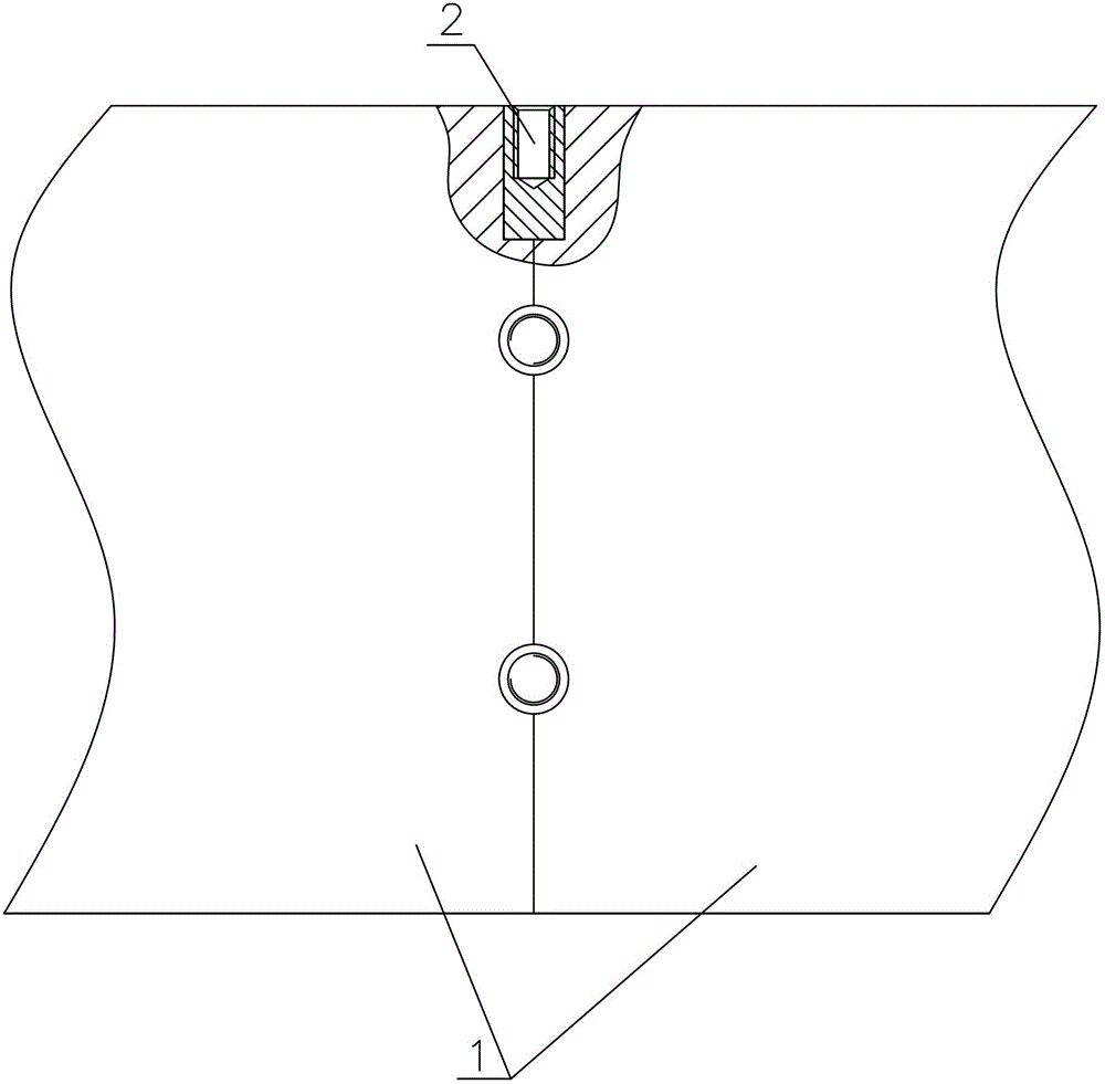
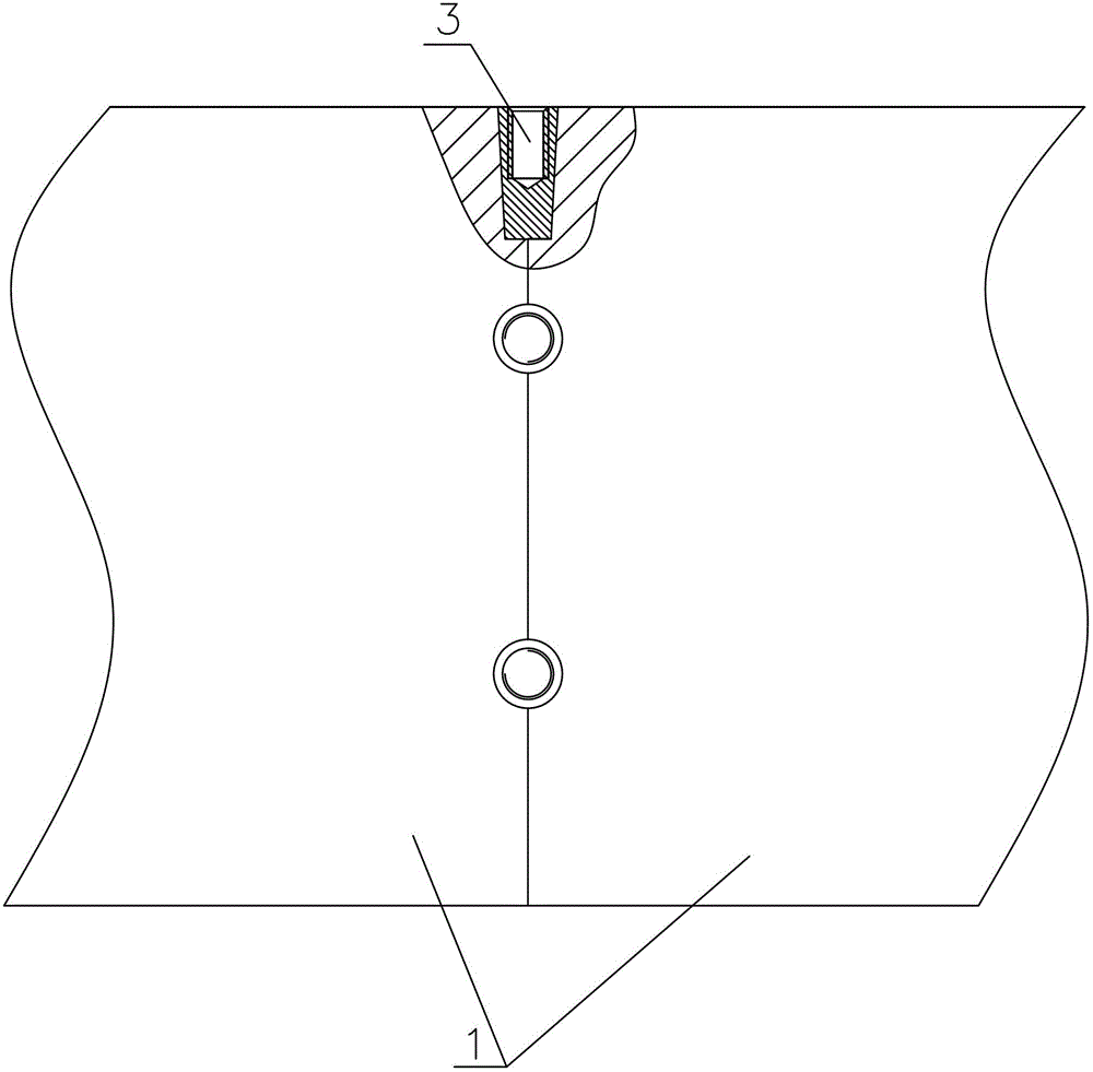
[0021] refer to figure 1 figure 2 , when installing on site, the first is the pre-installation of the ground, butt the two beams on the ground, adjust the upper surface of the two beams and the left and right sides to align with each other, and then install guide rails and racks on both sides of the two beams. The connecting plate is fixed between them; the upper end surface of the beam and the left and right end surfaces have semi-cylindrical holes, and the semi-cylindrical holes of the beam at the butt joint are spliced ​​to form the entire cylindrical hole, and a cylindrical pin is driven into the cylindrical hole for positioning;

[0022] The following is the installation work in the air. When hoisting the beam to the robot support, remove the guide rail, rack and connecting plate at the joint of the beam, and take out the cylindrical pin at the same time, separate the two beams and lift them up; The crossbeams are slowly approached for docking, and the cylindrical pins ...


PUM


Abstract

The invention relates to a large-size cross beam mounting method, comprising the steps that pre-mounting is carried out on ground firstly; a round pin is inserted into a cylindrical hole in the joint part of two cross beams; when the two cross beams are mounted on a support of a robot, lifting is carried out in the air; guide rails, racks and a connecting plate at the joint part of the cross beams are detached; meanwhile, the round pin is taken out; the two sections of cross beams are separated and lifted; the lifted cross beams slowly approaches and the butt joint is carried out; the round pin is inserted into the cylindrical hole in the joint part so as to complete positioning; then the two cross beams are subjected to close butt joint; the guide rails and the racks are mounted on the two sides of the cross beams; after the step f is completed, the round pin is pulled out; a Morse taper broach reamer is used for reaming the cylindrical hole into a Morse taper hole; and a taper pin is inserted into the Morse taper hole so as to complete the butt joint mounting of the whole cross beam. The concept of secondary mounting is introduced, and the round pin is added to replace the taper pin for positioning; during butt joint, not only is the positioning function realized, but also the anti-shearing effect is realized; and the precision of the butt joint mounting of the cross beam can be ensured through using the method.

Description

technical field [0001] The invention relates to the technical field of on-site installation of large beams, in particular to the field of truss robots, and in particular to a method for installing large beams. Background technique [0002] The beam of the truss robot is used as a load-bearing part and is also equipped with guide rails. The main shaft of the robot is slidably connected to the guide rails on both sides of the beam. Generally, the truss robot is divided into X-axis and Z-axis. The guide rails on both sides of the beam are responsible for the X-axis. Mobile, because for large robots, the beam will be huge in terms of tonnage and length, so the guide rails on both sides of the beam are installed in sections, so whether the guide rails are connected smoothly will affect the movement of the X-axis, and the guide rails Whether the installation is smooth or not also depends on whether the connection between the beams is stable and flat. At present, the installation m...

Claims


Application Information

Patent Timeline
Patent Type & Authority Patents(China)
IPC IPC(8): B23P21/00
Inventor 司文凯
Owner STON ROBOT CHANGZHOU
Why Eureka
Try Eureka