
Locking and fixing device

A technology for locking devices and fixing parts, which is applied in the direction of support structure installation, fixed base/bracket of solar collectors, photovoltaic modules, etc., which can solve problems such as inconvenient installation and achieve the effect of convenient locking and installation

Inactive Publication Date: 2013-09-25
富昱能源科技(昆山)有限公司 +1
View PDF0 Cites 1 Cited by
  • Summary
  • Abstract
  • Description
  • Claims
  • Application Information

AI Technical Summary

Problems solved by technology

If you forget to put it in or put it in less, you need to remove the photovoltaic module and then put it into the locking structure, which is very inconvenient to install

Method used


Image

  • Locking and fixing device
  • Locking and fixing device
  • Locking and fixing device

Examples


Embodiment Construction

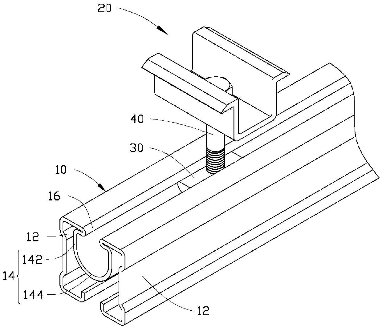
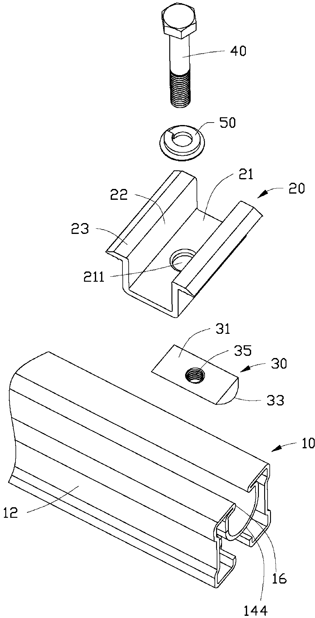
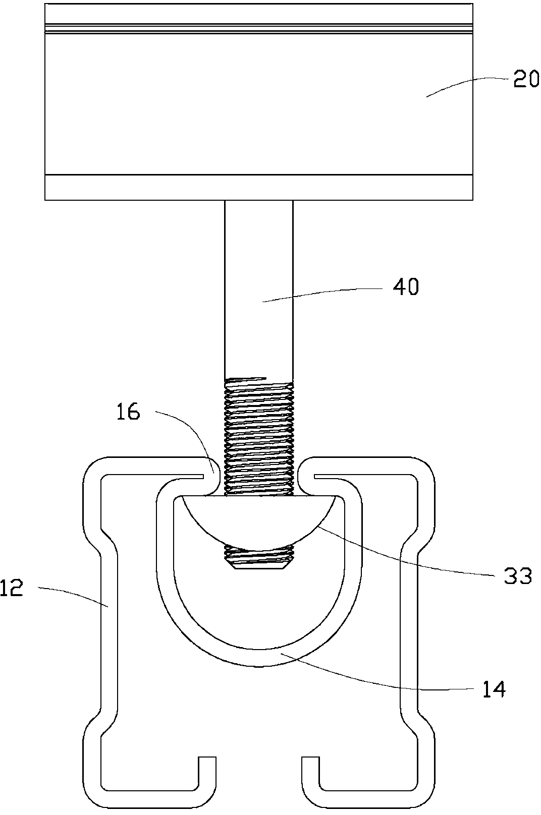
[0013] see Figure 1 to Figure 3 A preferred embodiment of the locking device of the present invention includes a strip-shaped bracket 10 , a pressing member 20 , a fixing member 30 , a screw rod 40 and an elastic washer 50 .

[0014] The cross-section of the bracket 10 is generally "concave" shape, and it includes two opposite side plates 12 and a guide groove portion 14 with a U-shaped cross-section between the two side plates 12 . The guiding groove portion 14 includes two opposite side walls 142 and a circular guiding portion 144 whose inner wall is arc-shaped. The two side plates 12 are in the shape of "【" and "】" respectively and are arranged opposite to each other. The top of each side wall 142 of the guide groove portion 14 is in contact with the top of the corresponding side plate 12 and protrudes inwardly to form a locking portion 16 protruding inside the guide groove portion 14 . A gap is formed between the two locking portions 16 .

[0015] The pressing member 2...


PUM


Abstract

A locking and fixing device comprises a support, a pressing piece, a fixing piece and a screw rod. The support comprises two side plates and a guide groove portion arranged between the two side plates, the guide groove portion comprises two opposite side walls and a guide portion with an arc-shaped inner wall, the top portion of each side wall of the guide groove portion is connected with the top of each corresponding side plate and protrudes inwards to form a clamping portion which protrudes and stretches into the guide groove portion, a clearance is formed between the two clamping portions, the fixing piece comprises a rectangular top face and an arc-shaped bottom face, a screw hole penetrating through the bottom face is formed in the center of the top face, the fixing piece is placed in the guide groove portion, the arc-shaped bottom face of the fixing piece and the guide portion are matched to enable the top face of the fixing piece to face upwards, and the screw rod is locked in the screw hole of the fixing piece after penetrating through the pressing piece and the clearance formed between the two clamping portions. Compared with the prior art, due to the fact that the arc-shaped bottom face of the fixing piece and the arc-shaped guide portion of the support are matched, the locking and fixing device enables the fixing piece to be capable of automatically adjusting after the fixing piece is placed in the guide groove portion, and the screw rod can be conveniently locked, fixed and mounted.

Description

technical field [0001] The invention relates to a locking device, in particular to a locking device for a photovoltaic module bracket. Background technique [0002] The photovoltaic module is usually locked on the bracket through a locking structure. The commonly used hexagonal nut cannot be automatically aligned after being placed in the guide groove of the bracket, and it is inconvenient to lock the stud. Therefore, the locking structure must be pre-assembled before the photovoltaic module is placed, and then installed on the bracket from the end of the bracket, and then moved to the position to be locked when locking. If you forget to put in or put in less, you need to remove the photovoltaic module and then put it into the locking structure, which is very inconvenient to install. Contents of the invention [0003] In view of the above, it is necessary to provide a locking device that is easy to install. [0004] A locking device, comprising a bracket, a pressing piec...

Claims


Application Information

Patent Timeline
Patent Type & Authority Applications(China)
IPC IPC(8): H05K7/14
CPCH02S20/00Y02E10/50Y02E10/47F24S25/30F24S2025/807F24S25/636
Inventor 陆恺民石戍刚
Owner 富昱能源科技(昆山)有限公司
Learn More