Semiconductor laser aging method and fixing clamp

A technology for fixing fixtures and lasers, used in semiconductor lasers, lasers, laser parts and other directions, can solve the problems of no automatic device and little application significance, and achieve the effect of easy operation, convenient operation and reduced burnout

Active Publication Date: 2015-06-24
Shandong Huaguang Optoelectronics Co. Ltd.
View PDF8 Cites 0 Cited by
  • Summary
  • Abstract
  • Description
  • Claims
  • Application Information

AI Technical Summary

Problems solved by technology

The design has no automatics and is of little interest for high-volume production applications

Method used


Image

  • Semiconductor laser aging method and fixing clamp
  • Semiconductor laser aging method and fixing clamp
  • Semiconductor laser aging method and fixing clamp

Examples


Embodiment 1

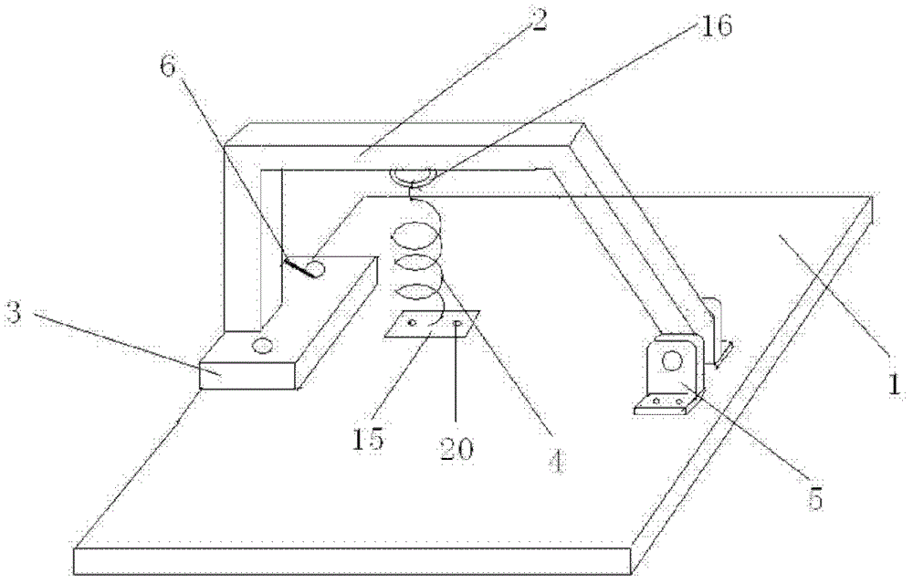
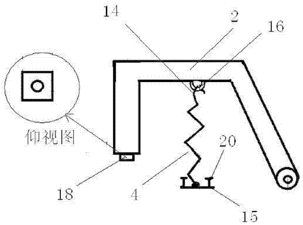
[0038] Embodiment 1: A kind of laser aging jig, the structure is as follows figure 1 -5 shown.

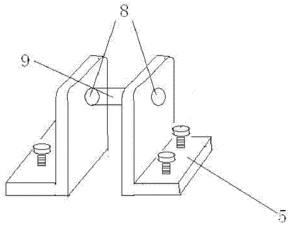
[0039] The laser aging fixture is mainly composed of a base 1, a fixed rod 2, a base 3, and a spring 4. The base 1 is used for fixing the base 3 , the fixing rod 2 and the spring 4 . The base 3 is fixed on the base by screws 7; the fixed rod 2 is a bow-shaped cross-arm structure, which is composed of a vertical arm, a horizontal arm and an oblique strut. In 9, the fixing piece includes two L-shaped angle irons 5, and there are shaft holes 8 on the L-shaped angle irons 5, and the fixed rod 2 is connected with the L-shaped angle irons through a circular shaft 9, and the L-shaped angle irons are fixed on the base On, whole fixed rod 2 can rotate up and down; Fixed rod 2 horizontal arms are provided with hanging ring 16, and the base just below this hanging ring 16 is fixed with cylindrical spring 4, and spring 4 upper end is provided with hook 14, is used for spring 4 is hung on t...

Embodiment 2

[0043] Embodiment 2. A semiconductor laser aging method, using the laser aging jig in Embodiment 1.

[0044] The structure of the laser is as Figure 6 As shown, the main structure includes heat sink 12 , transition electrode sheet 11 , screw hole 13 , and tube core 19 .

[0045] Proceed as follows:

[0046] (1) if Figure 7 As shown, the heat sink 12 equipped with the laser is placed in the groove 10 of the base 3, and then the transition electrode sheet 11 of the laser is fixed on the negative electrode sheet 17 of the base 3 with a clip bar 6, and then the fixing rod The bottom surface of the end of the vertical arm of 2 is pressed on the laser heat sink 12, and the hook 14 of the spring 4 is hung in the hanging ring 16 on the cross arm of the fixed rod 2, and the spring 4 provides downward pressure for the vertical arm of the fixed rod 2, The end of the vertical arm of the fixing rod 2 is pressed against the heat sink 12 of the laser.

[0047] (2) The negative electrod...

Embodiment 3

[0049] There are several working units on one base at the same time. When making the aging fixture, the size of the base can be increased, and then multiple sets of aging devices consisting of bases, fixing rods and springs as described in Embodiment 1 can be installed on one base. The working unit mechanism increases the actual utilization value of the fixture and is more conducive to industrial production. The specific aging method is then the same as in Example 2.


PUM


Abstract

The invention relates to a semiconductor laser aging method and fixing clamp. A conductive substrate of the laser aging fixing clamp is fixedly arranged on the edge of a base, a groove is formed in the outer edge of the substrate, a negative electrode slice is pasted on the substrate, and a fixing clamping strip is used for clamping a laser transitional electrode splice on the negative electrode splice. A fixing rod can rotate up and down, a hanging ring is arranged on the cross arm of the fixing rod, a spring is fixedly arranged on the base, the spring is hung on the hanging ring of the fixing rod through a hook, and downward pressure is provided by a fixing rod vertical arm. A heat sink with a laser is placed on the groove of the base, the transitional electrode splice of the laser is fixedly arranged on the negative electrode splice of the substrate through the clamping strip, the bottom face of the end portion of the fixing rod vertical arm presses the laser heat sink, the negative electrode splice of the substrate is communicated with the negative electrode of a power supply, and one screw of the substrate is communicated with the positive electrode of the power supply. According to the semiconductor laser aging method and fixing clamp, the aging yield and the aging efficiency of the semiconductor laser are improved.

Description

technical field [0001] The invention relates to an aging method and a fixing fixture of a semiconductor laser, belonging to the field of semiconductor laser devices. Background technique [0002] Semiconductor laser is a type of laser that matures earlier and develops faster. It has a wide wavelength range, is simple to manufacture, low in cost, easy to mass produce, and has a wide range of applications. The application range of semiconductor lasers covers the entire field of optoelectronics, and has become the core technology of optoelectronic science today. Semiconductor lasers have been widely used in laser ranging, laser radar, laser communication, laser simulation weapons, laser warning, laser guidance and tracking, ignition and detonation, automatic control, detection instruments, etc., forming a broad market. In 1978, semiconductor lasers began to be used in optical fiber communication systems. Semiconductor lasers can be used as light sources and indicators for opt...

Claims


Application Information

Patent Timeline
Patent Type & Authority Patents(China)
IPC IPC(8): H01S5/00
Inventor 王魁李沛旭
Owner Shandong Huaguang Optoelectronics Co. Ltd.
Why Eureka
Try Eureka