Three-terminal electrical connector and method of use thereof

A connector and electrical technology, which is applied in the field of improvement of electrical connectors for circuits and their use methods, and can solve the problems of inability to meet the requirements of three ports and the like

Active Publication Date: 2015-09-02
SHANGHAI HUALI MICROELECTRONICS CORP
View PDF3 Cites 0 Cited by
  • Summary
  • Abstract
  • Description
  • Claims
  • Application Information

AI Technical Summary

Problems solved by technology

This structure cannot meet the requirements of three ports for occasions that require a third port, such as when an oscilloscope is introduced to monitor nodes.

Method used


Image

  • Three-terminal electrical connector and method of use thereof
  • Three-terminal electrical connector and method of use thereof
  • Three-terminal electrical connector and method of use thereof

Examples


Embodiment Construction

[0024] The invention will now be described in more detail with reference to the accompanying drawings, in which preferred embodiments of the invention are shown, it being understood that those skilled in the art may modify the invention described herein and still achieve the beneficial effects of the invention. Therefore, the following description should be understood as the broad knowledge of those skilled in the art, but not as a limitation of the present invention.

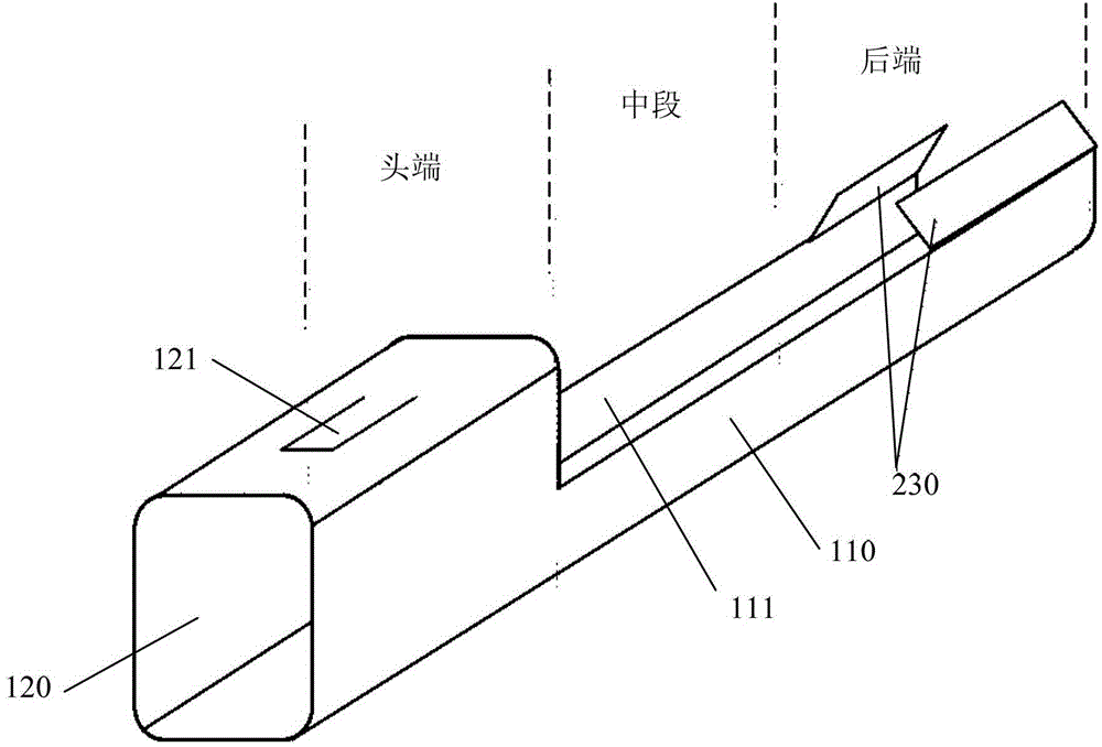
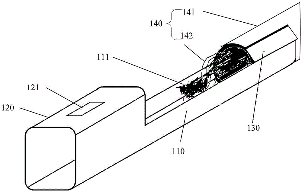
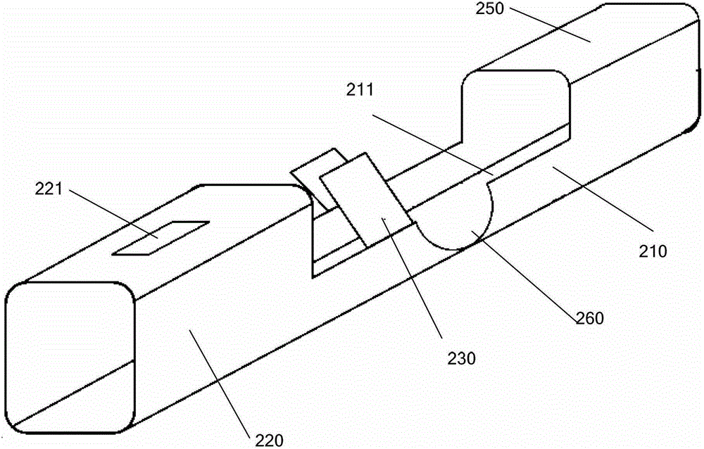
[0025] see image 3 and Figure 4 ,in, image 3 Shown is a schematic structural view of a three-terminal electrical connector according to an embodiment of the present invention, Figure 4 Shown is a schematic view of the use state of the three-terminal electrical connector according to an embodiment of the present invention. A three-terminal electrical connector provided in this embodiment includes a connector body 210 with a groove 211 and a pair of wing-shaped fixing pieces 230. The front and rear ends of...


PUM


Abstract

The invention discloses a three-terminal electrical connector assembly. The three-terminal electrical connector assembly comprises a connector assembly body and a pair of wing-shaped fixing pieces, wherein the connector assembly body is provided with a groove. The front end and the back end of the connector assembly body are provided with a front end sleeve and a back end sleeve respectively. The front end sleeve and the back end sleeve are respectively communicated with the groove. An opening is formed in the top of the front end sleeve. A clamping opening into which a metal wire can stretch is formed in the middle of one side wall of the groove in the connector assembly body. The wing-shaped fixing pieces are correspondingly arranged on the two side walls of the groove, and are located between the front end sleeve and the clamping opening. A pin header can be fixed through the front end sleeve, one metal wire can be fixed through the back end sleeve, and another metal wire can be fixed through the clamping opening so that the three terminals can be selectively connected and changing and monitoring of a node can be achieved conveniently.

Description

technical field [0001] The invention belongs to the field of electronic engineering, and relates to the improvement of an electrical connector for a circuit and its use method. Background technique [0002] See figure 1 and figure 2 ,in, figure 1 Shown is a schematic structural diagram of an existing electrical connector, figure 2 Shown is a schematic diagram of the use state of the existing electrical connectors. The existing metal connectors include a connector body 110 with a groove 111, and a head end sleeve 120. The head end sleeve can be used to connect pin headers, etc. part. The top of the head-end sleeve 120 is provided with a buckle 121 for clamping the metal connector on the plastic shell (not shown) to achieve mutual fixing between the two. The tail end of the metal connector is a semi-open semi-section barrel wall structure, which can be connected to the metal wire 240 stripped of the plastic shell and fixed by the wing-shaped fixing piece 130. The metal ...

Claims


Application Information

Patent Timeline
Patent Type & Authority Patents(China)
IPC IPC(8): H01R13/02
Inventor 柯遥
Owner SHANGHAI HUALI MICROELECTRONICS CORP
Why Eureka
Try Eureka