
A hole box type floating breakwater with built-in buoyancy unit

A floating breakwater and buoyancy unit technology, applied in the directions of breakwaters, embankments, jetties, etc., can solve the problems of incompatible distribution rules, water circulation restrictions, water pollution in the port, etc. cost reduction effect

Active Publication Date: 2016-08-10
JIANGSU UNIV OF SCI & TECH +1
View PDF5 Cites 2 Cited by
  • Summary
  • Abstract
  • Description
  • Claims
  • Application Information

AI Technical Summary

Problems solved by technology

However, the traditional types of breakwaters (vertical and slope) are completely incompatible with the distribution of wave energy in the use of materials.
For example, the slope type breakwater uses the least material in the place where the wave energy is the most concentrated, but consumes a lot of material in the place where the wave energy is the smallest. With the increase of the depth of the project water area, the project cost increases sharply, and the construction becomes more complicated. very difficult
Moreover, the water circulation in the shelter area is limited, and it is easy to cause sediment deposition, coastal changes, and water pollution in the port.
[0004] For ordinary pontoon-type floating breakwaters and buoy-type floating breakwaters, when the external structure cracks and seeps water, the floating breakwater will lose its buoyancy, which will eventually cause the floating breakwater to sink into the seabed and lose its operating capacity.

Method used


Image

  • A hole box type floating breakwater with built-in buoyancy unit
  • A hole box type floating breakwater with built-in buoyancy unit
  • A hole box type floating breakwater with built-in buoyancy unit

Examples


Embodiment Construction

[0025] The present invention will be further described below in conjunction with the accompanying drawings.

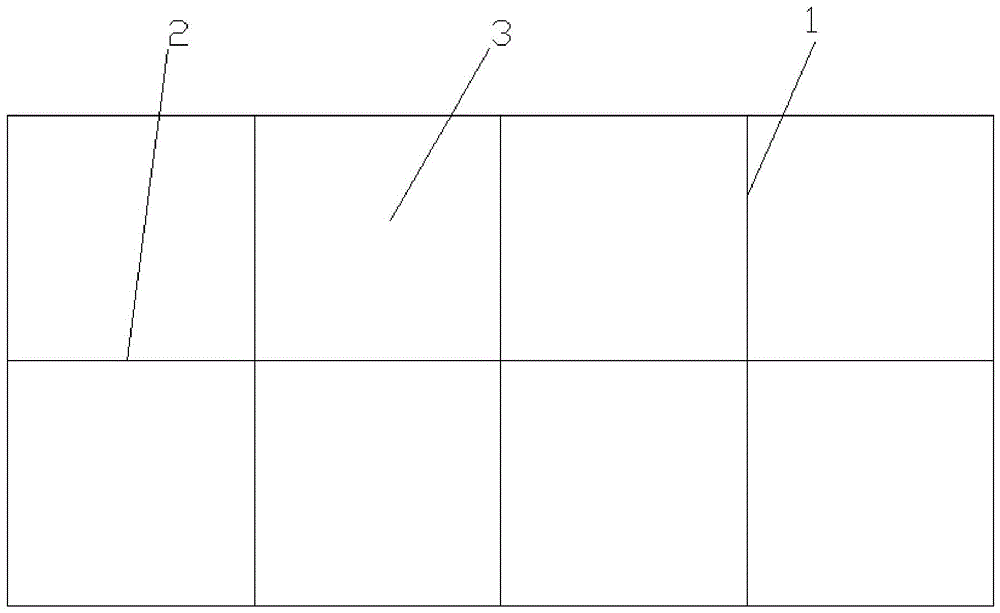
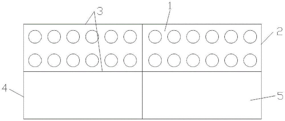
[0026] Such as Figure 1 to Figure 8 As shown, a perforated box-type floating breakwater with a built-in buoyancy unit of the present invention includes an open-hole box structure, a buoyancy unit and an anchoring device; the buoyancy unit is placed inside the open-hole box structure, and the anchoring device is symmetrically arranged on On both sides of the open-hole box structure; the open-hole box structure includes a number of porous rigid plates, a number of rigid plates and a number of rigid support columns 6, and the porous rigid plates and rigid plates are vertically arranged in pairs and rigidly connected to form an open-hole box body structure, the rigid support columns 6 are installed in parallel at the bottom of the perforated box structure; the upper half of the perforated box structure is located on the waterline, and the lower half is located below the w...


PUM


Abstract

The invention discloses a perforated case type floating breakwater with a built-in buoyancy unit. The perforated case type floating breakwater comprises a perforated case structure, the buoyancy unit and anchoring devices; the buoyancy unit is arranged inside the perforated case structure, and the anchoring devices are symmetrically arranged on two sides of the perforated case structure; the perforated case structure comprises a plurality of porous rigid plates, rigid plates and rigid support columns, the porous rigid plates and the rigid plates are perpendicular to one another pairwise and are rigidly connected with one another to form the perforated case structure, and the rigid support columns are parallelly mounted at the bottom of the perforated case structure; the buoyancy unit comprises a plurality of rubber pieces, air is filled in each rubber piece, and the rubber pieces are arranged inside the lower half portion of the perforated case structure. The perforated case type floating breakwater has the advantages that stable and reliable buoyancy can be provided, so that accidents that the traditional case type floating breakwater is sunken into a seabed due to loss of buoyancy when cracks are formed in an outer structure of the traditional floating breakwater and water seeps into the traditional floating breakwater are prevented, materials are effectively saved, the cost is lowered, draft of the breakwater can be adjusted, a wave absorbing effect is improved, and the perforated case type floating breakwater can be applied to water areas where piling anchoring cannot be implemented.

Description

technical field [0001] The invention relates to the technical field of breakwaters, in particular to a perforated box type floating breakwater with a built-in buoyancy unit. Background technique [0002] Breakwater is a common port and coastal engineering structure, which is used to prevent the invasion of waves on the port area, maintain the stability of the waters in the port, and ensure the safe berthing, mooring, normal loading and unloading operations of ships and passengers going up and down in the port. [0003] According to the research and experiment of the wave theory, the energy of the wave is concentrated on the surface of the water body, and 98% of the total wave energy is concentrated in the depth range of three times the wave height below the water surface. However, the use of materials for traditional breakwaters (vertical and sloped) is completely incompatible with the distribution of wave energy. For example, the slope type breakwater uses the least materi...

Claims


Application Information

Patent Timeline
Patent Type & Authority Patents(China)
IPC IPC(8): E02B3/06
CPCY02A10/11
Inventor 嵇春艳陈翔田超陆晔刘珍倪钦韵马小剑严琦
Owner JIANGSU UNIV OF SCI & TECH
Learn More