Pump

A pump chamber and canned pump technology, applied in the field of pumps, can solve the problem of high installation cost, and achieve the effect of simple manufacturing technology, saving space and reducing installation cost

Inactive Publication Date: 2013-09-18
HANNING ELECTRO WERKE GMBH & CO KG
View PDF8 Cites 4 Cited by
  • Summary
  • Abstract
  • Description
  • Claims
  • Application Information

AI Technical Summary

Problems solved by technology

The disadvantage of this known pump is that the installation effort is relatively high in the region of the first end face of the motor housing facing the pump chamber.

Method used


Image

  • Pump

Examples


Embodiment Construction

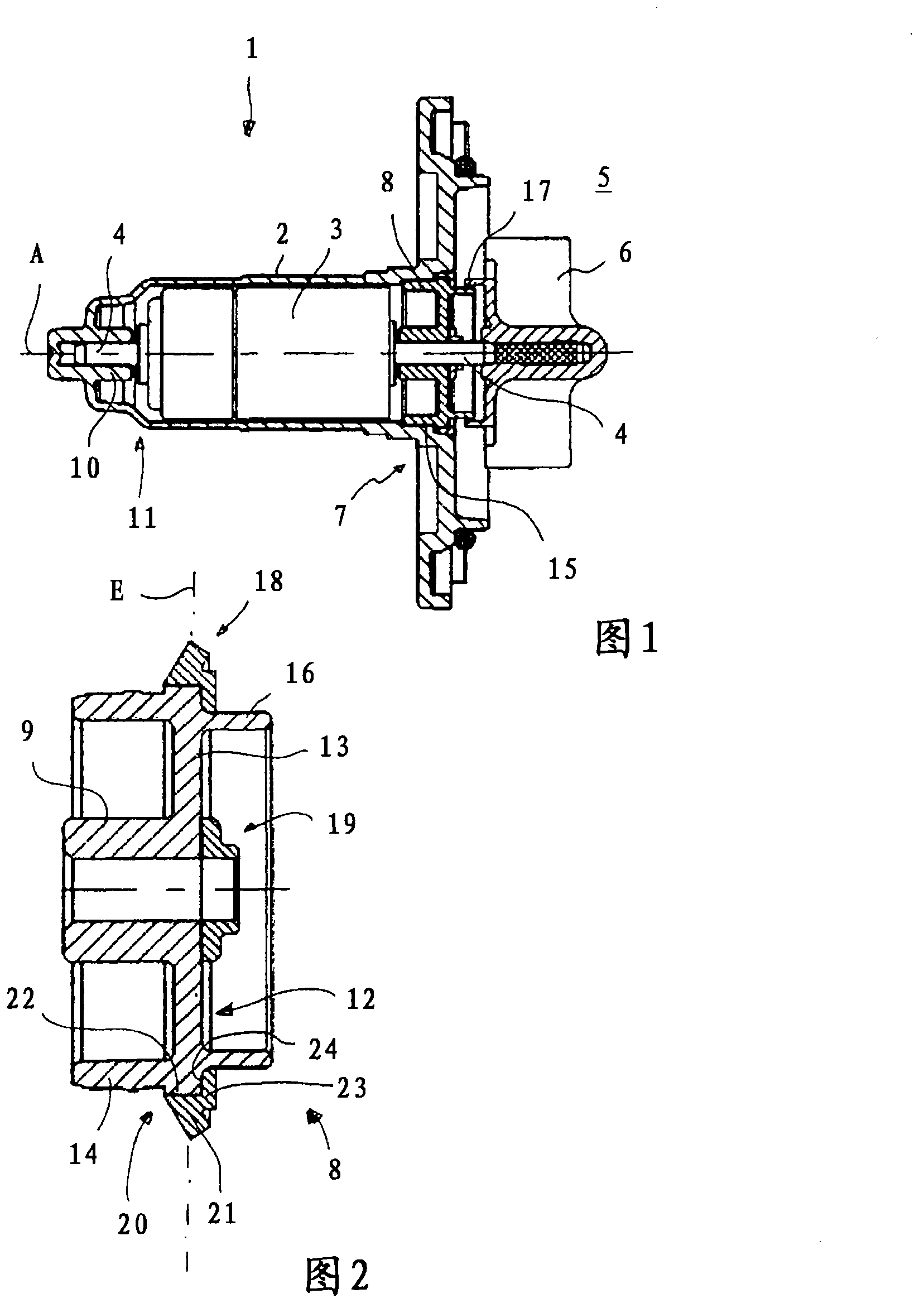
[0016] The pump according to the exemplary embodiment of the invention shown in the drawing forms a canned pump 1 that can preferably be used in domestic appliances that operate with water, such as dishwashers or the like.

[0017] The canned pump 1 has a canned tube 2 as a motor housing, in which a rotor 3 of a synchronous motor and a drive shaft 4 connected to the rotor 3 in a non-rotatable manner are mounted. The not shown stator of the synchronous motor can be arranged outside this shielding tube 2 .

[0018] The drive shaft 4 is non-rotatably connected to the impeller 6 of the pump, which is arranged in the pump chamber 5 . Alternatively, the drive shaft 4 can also be connected to the impeller 6 of the pump via a freewheel or via a flywheel.

[0019] In the region of the first end face 7 of the shielding tube 2 facing the pump chamber 5 , a sealing carrier 8 is arranged, which has a supporting and sealing function. from figure 2 As can be seen more clearly in , the on...


PUM


Abstract

The invention relates to a pump, especially a shield pump used for conveying liquid into a home appliance operating with water. The pump comprises a stator, a rotor, and a drive shaft. The drive shaft is non-rotatably coupled to a running wheel arranged in pump compartment, and is rotatably arranged inside a motor casing through a bearing unit. A sealing device is dispsoed on a first end surface of the motor casing, facing towards the pump compartment, and is used for isolating the motor casing from the pump compartment in a sealing manner. The bearing unit and the sealing device are formed and arranged on the first end surface (7) of the motor casing (2) by means of a sealing support body (8). The sealing support body comprises an axial shaft sleeve part segment for being slidingly supported by the drive shaft (4), a radial sealing segment for shielding the motor casing, and at least a flexible sealing element formed on the axial shaft sleeve segment and / or the radial sealing segment.

Description

technical field [0001] The invention relates to a pump, in particular a canned pump, for conveying liquids into domestic appliances or the like which are operated with water, the pump having a stator, a rotor and a drive shaft which is rotatably fixed to a pump The working wheel in the chamber is connected, the drive shaft is rotatably supported in the motor housing through the supporting device, and the sealing device is arranged on the first end face of the motor housing facing the pump chamber, which is used to connect the motor housing with the pump chamber. The pump chamber is sealed and isolated. Background technique [0002] DE 38 23 461 A1 discloses a pump for a water-operated domestic appliance, which has, on the one hand, an electric motor housing with an integrated stator and rotor and, on the other hand, an impeller arranged outside the electric motor housing. The impeller is fixedly connected to the drive shaft of the electric motor. [0003] The drive shaft i...

Claims


Application Information

Patent Timeline
IPC IPC(8): F04D29/10
CPCF04D13/0613F04D29/047F04D29/126F01D25/16
Inventor N·克罗格迈尔
Owner HANNING ELECTRO WERKE GMBH & CO KG
Why Eureka
Try Eureka