
Double-layer bidirectional pre-tensioned track plate

A track board, double-layer technology, applied in the field of track boards, can solve the problems of increasing the number of board factories and labor costs, low production efficiency, and no independent intellectual property rights.

Inactive Publication Date: 2013-09-18
欧阳炎
View PDF6 Cites 7 Cited by
  • Summary
  • Abstract
  • Description
  • Claims
  • Application Information

AI Technical Summary

Problems solved by technology

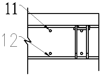
[0012] (1) CRTS I and CRTS II type track slab transverse prestressed steel rods (or steel bars) are arranged at the neutral axis position of the section (photo 11, 12). When the track slab is bent, the strength of the prestressed steel cannot be effectively exerted, so In addition to prestressed steel rods (or steel bars), non-prestressed steel cages (or steel mesh sheets) must be configured to supplement the deficiencies in the bending capacity of the plate (Photo 13)
This not only greatly increases the amount of steel used and man-hours, but also adversely affects the durability of the track slab (insufficient thickness of the protective layer) and the signal circuit (insulation performance)
[0013] (2) Since the width of the track slab is only 2.5 meters, if the post-tensioning process is adopted, the retraction of the steel bar and the deformation of the anchorage will cause a large loss of prestress, reduce the effective precompression stress of the concrete, and cause the crack resistance of the track slab ( Especially the fatigue crack resistance) ability is significantly reduced
[0014] (3) The CRTS II plate is not prestressed longitudinally, so it is impossible to avoid a large number of transverse cracks (photo 14)
[0023] (1) Too much steel consumption: CRTS I and CRTS II track slabs must be equipped with non-prestressed steel cages (or mesh) to supplement the lack of bending resistance of the slabs. The steel cages account for the total of CRTS I track slabs 1 / 2~3 / 4 of steel consumption;
[0024] (2) The insulation cost of the steel cage (or mesh);
[0025] (3) Anchors and anchor pads are required for CRTS I-type plates;
[0026] (4) The production efficiency of the CRTS I-type panel factory is low, which increases the number of panel factories and labor costs;
[0030] (1) Single track limit method, poor adaptability and inconvenient application
[0031] (2) CRTS I-type boards and frame boards can only be manufactured in a single piece, and cannot get rid of the backward production technology of manual workshops, and it is difficult to realize industrialization and automation
[0032] (3) CRTS I and CRTS II track slabs are imported from abroad, without independent intellectual property rights, and cannot meet the requirements of my country's high-speed rail complete technology competition in the international market

Method used


Image

  • Double-layer bidirectional pre-tensioned track plate
  • Double-layer bidirectional pre-tensioned track plate
  • Double-layer bidirectional pre-tensioned track plate

Examples


Embodiment 1

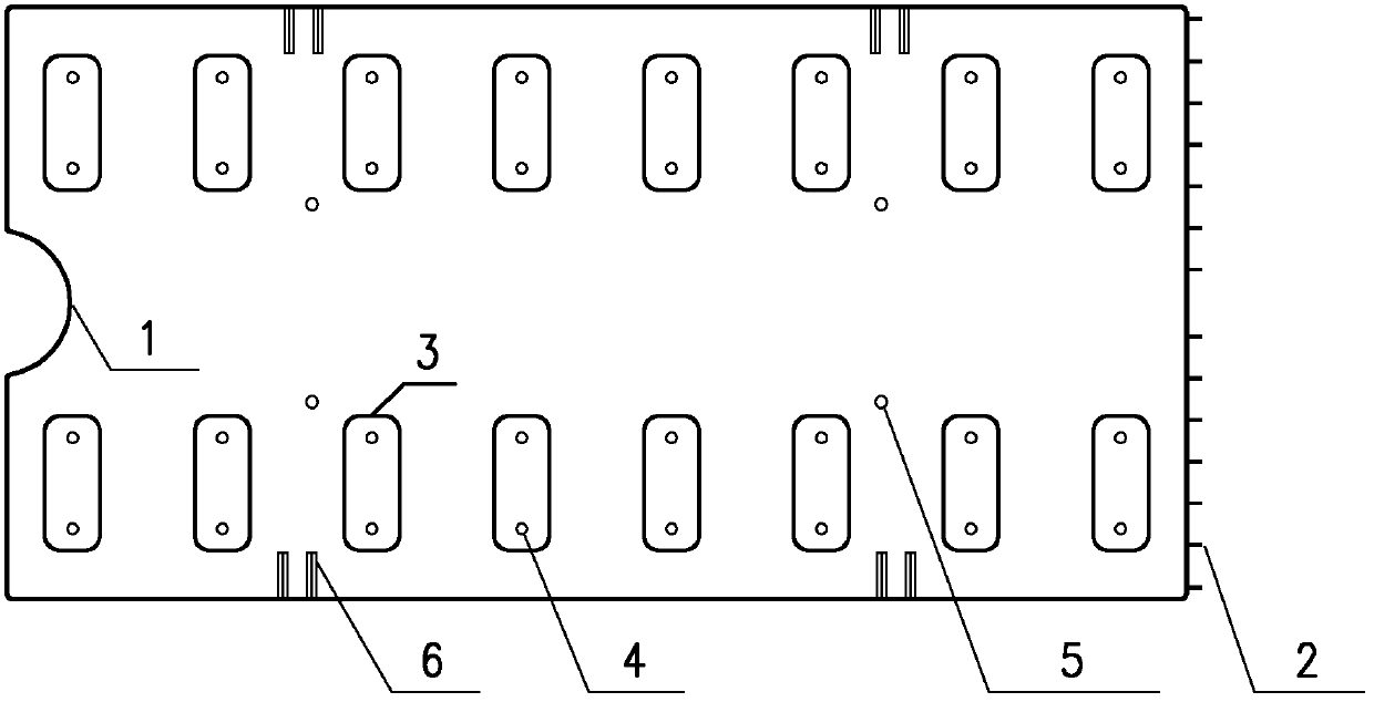
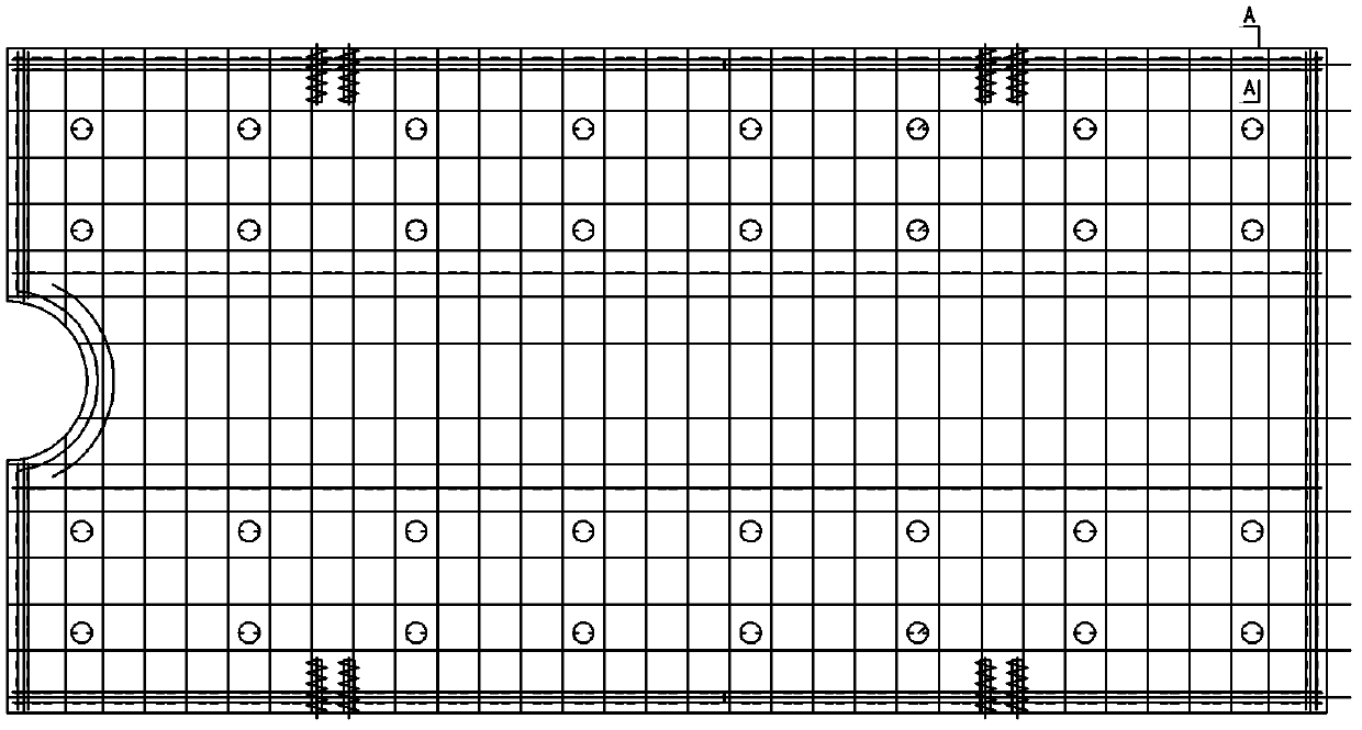
[0069] Such as Figure 1 ~ Figure 3 As shown, the CRTS I-type track plate includes a concave limit groove 1, and the concave limit groove 1 is located at one end of the CRTS I-type track plate in the length direction, and is used for cooperating with the convex block to limit the position; the CRTS I-type track plate The other end in the length direction is provided with a longitudinal connector 2, which is used for the connection of two adjacent CRTS I-type track slabs. Above the CRTS I-type track slab, there are two rows of parallel rail bottoms 3, and the rail bottoms 3 are embedded The bushing 4 is fixedly connected to the CRTS I-type track slab, and there is a mortar pouring hole 5 above the CRTS I-type track slab, and there are lifting sleeves 6 on both sides of the CRTS I-type track slab for the laying and installation of the CRTS I-type track slab;

[0070] A layer of transverse prestressed reinforcement group 12 and a layer of longitudinal prestressed reinforcement gr...

Embodiment 2

[0073] The specific implementation of embodiment 2 is the same as that of embodiment 1, the difference is that embodiment 2 adopts CRTS II track slabs, and a layer of transverse prestressed steel bar group 12 and a layer of longitudinal Prestressed reinforcement group 11; longitudinal prestressed reinforcement group 11 is distributed in the same horizontal plane of CRTS II type track slab; transverse prestressed reinforcement group 12 is distributed in the same horizontal plane of CRTS II type track slab; The distance between the longitudinal prestressed reinforcement group 11 and the transverse prestressed reinforcement group 12 is not less than 6 mm; two vertical stirrups are respectively arranged in the prestressed reinforcement anchorage area around the CRTS II track slab. The middle part is longitudinally symmetrical along the track slab, and there is also a vertical stirrup in the center of the slab, and an insulating layer is provided outside the six vertical stirrups, s...


PUM


Abstract

The invention relates to a track plate, in particular to a double-layer bidirectional pre-tensioned track plate, which comprises a track plate, wherein the track plate is symmetrically provided with a layer of transverse pre-stressed reinforcement set and a layer of longitudinal pre-stressed reinforcement set on the two sides about the neutral axis respectively; the longitudinal pre-stressed reinforcement sets are distributed in the same horizontal plane of the track plate; the transverse pre-stressed reinforcement sets are distributed in the same horizontal plane of the track plate; the clear spacing between the longitudinal pre-stressed reinforcement set and the transverse pre-stressed reinforcement set on the same side of the track plate is not less than 6 mm; two vertical stirrups are arranged in a pre-stressed reinforcement anchoring region around the track plate respectively; the middle part of the track plate is also symmetrically provided with a vertical stirrup along the longitudinal direction of the track plate about the plate center; an insulating layer is arranged on the outer side of the vertical stirrups.

Description

technical field [0001] The invention relates to a track slab, in particular to a double-layer bidirectional pretensioned track slab. Background technique [0002] In 1964, Japan's Shinkansen came out; in 1981, France's TGV system was opened; in 1989, Germany's ICE high-speed train was put into operation. The high-speed rail technology of these three countries is relatively developed, and the track structure is relatively mature, which is representative to a certain extent. [0003] Japan's high-speed rail adopts slab-type ballastless track, and the track slabs that are finally put into engineering applications are mainly two-way post-tensioned prestressed slabs (photo 1) and hollow lattice slabs, also known as frame slabs (photo 2). The hollow lattice slab is lattice-shaped on the plane, and the frame slab is formed by longitudinal concrete strip members under two steel rails and multiple transverse connecting members. Such members can be prestressed or non-prestressed. ...

Claims


Application Information

Patent Timeline
Patent Type & Authority Applications(China)
IPC IPC(8): E01B1/00
Inventor 欧阳炎
Owner 欧阳炎
Learn More