
The nailing gun with the striker separated from the nail in advance

A technology for nailing guns and nails, which is applied in the field of nailing guns, and can solve problems such as the nailing gun is prone to failure, the striker cannot be released, and the nails are not squeezed normally.

Inactive Publication Date: 2016-04-06
APEX MFG
View PDF9 Cites 2 Cited by
  • Summary
  • Abstract
  • Description
  • Claims
  • Application Information

AI Technical Summary

Problems solved by technology

[0003] This type of nailer is prone to failure in actual use
Since the mechanism of this type of nailing gun to release the striker is achieved by the automatic separation of the swinging connecting rod and the linearly moving striker, when the connecting rod is worn out due to long-term use, the timing of the release of the striker will be advanced, and shrapnel may occur. Insufficient power storage and inaccurate nail firing
Secondly, if the position of the striker and the connecting rod is slightly changed due to production errors or impact by external force, the timing of the release of the striker will be changed, and it may even happen that the striker cannot be released.
[0004] In addition, when this type of nailing gun is not in use, the striker plate remains at the fired position and keeps in contact with the nail needle in the nail gun. After the striker plate is moved by the connecting rod, the nail needle moves forward to the correct position. Only in this position can the needle be fired smoothly. If the user uses it quickly and continuously, the striker will easily hit downward before the needle moves to the correct position, causing the needle to be squeezed abnormally, blocking the exit of the needle. cause damage

Method used


Image

  • The nailing gun with the striker separated from the nail in advance
  • The nailing gun with the striker separated from the nail in advance
  • The nailing gun with the striker separated from the nail in advance

Examples


Embodiment Construction

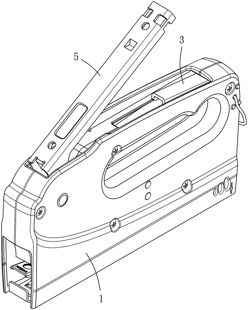
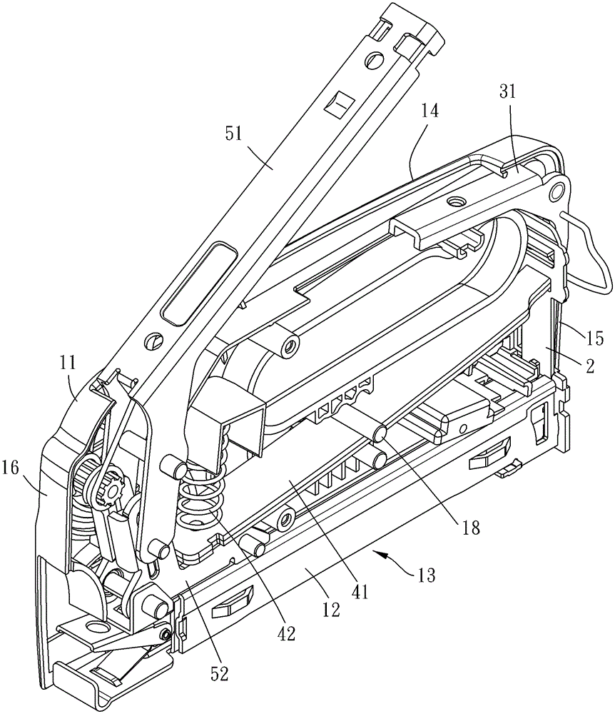
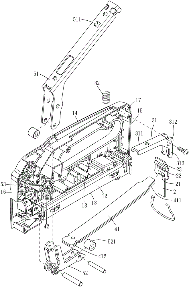
[0024] Please refer to figure 1 , The present invention provides a nailing gun, which is equipped with a nail, and accumulates the force required for driving the nail by manual pressing, which can be pressed by the user to drive out the nail. Please refer to Figure 1 to Figure 3 , The nailing gun provided by the present invention includes a housing 1 , a striking plate 2 , a limiting mechanism 3 , a power storage mechanism and an operating mechanism 5 .

[0025] The casing 1 mainly includes two half-shells 11 and a nail box 12, the half-shells 11 are fixed to each other by screws for the nail box 12 to be installed therein, and for further installation of other components, the shell has the ability to abut against objects and provide The bottom side 13 driven by the nail needle, the top side 14 corresponding to the bottom side, and the corresponding front end 15 and rear end 16, the nail box 12 is filled and entered by the rear end 16, so that the nail needle can be adjacent...


PUM


Abstract

The invention provides a nailing gun having a hitting board separated from a nail needle in advance. The nailing gun has a hitting board used for cocking a nail needle, a limiting mechanism, a force accumulation mechanism and an actuating mechanism, the limiting mechanism can maintain the hitting board in the initial position, the actuating mechanism can realize actuation and allows the force accumulation mechanism to accumulate elastic force potential energy, and the hitting board bears the elastic force of the force accumulation mechanism after the limiting mechanism is triggered in order to cock the nail needle, so the maintenance of the hitting board in the initial position in advance in the elastic force potential energy accumulation process of the force accumulation mechanism is realized, and the hitting board is separated from the nail needle, thereby the nail needle can move to a fixed position, and the false nailing possibility during continuous nail needle cocking can be reduced.

Description

technical field [0001] The invention relates to the technical field of engineering equipment, in particular to a nailing gun in which a striking plate is separated from a nail needle in advance. Background technique [0002] Known nail guns can refer to US5505362, US5816470 and US6789719 patents, which mainly use the swing of the grip to drive the connecting rod inside the nail gun to swing, and move the linear sliding striker to the position to be fired. When moving toward the position to be fired, the shrapnel is bent to accumulate force. When the connecting rod further swings and separates from the striker plate, the striker plate is quickly moved downward by the elastic force of the shrapnel, and the needle fire. [0003] Such nail guns are prone to breakdowns during actual use. Since the mechanism of this type of nailing gun to release the striker is achieved by the automatic separation of the swinging connecting rod and the linearly moving striker, when the connectin...

Claims


Application Information

Patent Timeline
Patent Type & Authority Patents(China)
IPC IPC(8): B25C5/00B25C5/11
Inventor 王景立
Owner APEX MFG
Learn More