
Zero current switch active equalization circuit of power batteries and implementation method

A power battery and zero-current technology, applied in battery circuit devices, circuit devices, current collectors, etc., can solve problems such as the inconsistency of battery cells in the battery pack that cannot be effectively eliminated, so as to improve the equalization efficiency and realize zero-current switch equalization , Improve the effect of inconsistency

Active Publication Date: 2013-09-11
SHANDONG UNIV
View PDF5 Cites 56 Cited by
  • Summary
  • Abstract
  • Description
  • Claims
  • Application Information

AI Technical Summary

Problems solved by technology

[0006] The purpose of the present invention is to overcome the problem that the inconsistency between the battery cells in the battery pack cannot be effectively eliminated in the above-mentioned prior art, and to provide a power battery zero-current switch active equalization circuit and its implementation method, which can judge the inconsistency of the battery pack in real time. The battery cells with the highest and lowest voltages are equalized by zero-current switching, because each equalization is for the two battery cells with the largest voltage difference in the battery pack to perform peak-shaving and valley-filling, which greatly improves the equalization efficiency. Thus effectively reducing the inconsistency between battery cells

Method used


Image

  • Zero current switch active equalization circuit of power batteries and implementation method
  • Zero current switch active equalization circuit of power batteries and implementation method
  • Zero current switch active equalization circuit of power batteries and implementation method

Examples


Embodiment Construction

[0032] The present invention will be further described below in conjunction with the accompanying drawings and embodiments.

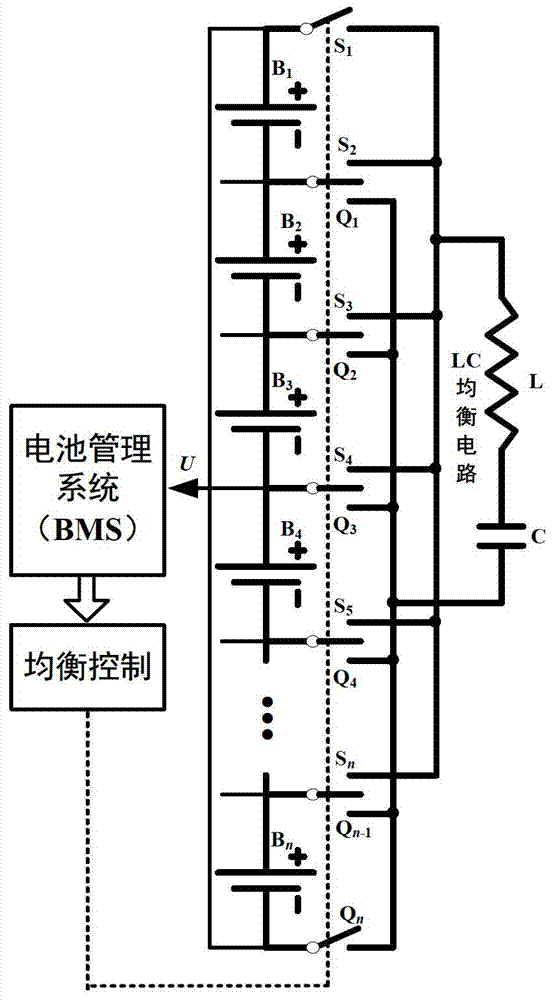
[0033] In view of the inconsistency between battery cells in the battery pack that cannot be effectively eliminated in related technologies, such as figure 1 As shown, the battery management system (BMS) can effectively eliminate the problem of inconsistency between battery cells in the battery pack through the technical solution of the present invention. The present invention proposes that the microcontroller collects the voltage signals of each battery cell by means of a voltage acquisition circuit, determines the battery cell with the highest voltage and the lowest voltage and judges whether the balance condition is met, and if the condition is satisfied, the microcontroller controls the balance switching circuit to switch the The LC quasi-resonant circuit is periodically switched between the battery cells with the highest voltage and the lowest volt...


PUM


Abstract

The invention discloses a zero current switch active equalization circuit of power batteries and an implementation method. Zero current switch equalization is performed on the two batteries with maximum voltage differences in a battery pack by utilizing an LC quasi-resonant circuit. The equalization circuit comprises an MCU (Microcontroller Unit), an equalization switching circuit and the LC quasi-resonant circuit. The equalization switching circuit is used for switching the LC quasi-resonant circuit between the batteries under the control of the MCU; the MCU obtains voltages of every power battery with the aid of a voltage acquisition circuit so as to determine a highest battery voltage and a lowest battery voltage and numbers of corresponding batteries, and if a maximum battery voltage difference value is larger than a battery equalization threshold value, the equalization circuit is started; in an equalization state, the MCU controls the equalization switching circuit to cyclically switch the LC quasi-resonant circuit between batteries of the highest voltage and the lowest voltage; and when a switching frequency emitted by the MCU is equal to a natural resonant frequency of an LC, the zero current switch equalization is achieved.

Description

technical field [0001] The invention relates to a new energy vehicle power control technology, in particular to a power battery zero-current switch active equalization circuit and an implementation method. Background technique [0002] At present, there are two types of dissipative and non-dissipative energy. The energy dissipation type achieves balance by connecting a resistor in parallel to each single battery in the battery pack to perform discharge shunting. Energy non-dissipative circuits use capacitors and inductors as energy storage elements, use common power conversion circuits as topological foundations, and adopt decentralized or centralized structures to realize unidirectional or bidirectional charging schemes. [0003] Energy-dissipating circuits are simple in structure, but there are problems of energy waste and thermal management. Energy non-dissipative circuits have disadvantages such as complex circuit structure, large volume, high cost, long equalization t...

Claims


Application Information

Patent Timeline
IPC IPC(8): H02J7/00
Inventor 张承慧崔纳新商云龙
Owner SHANDONG UNIV
Learn More