Directional current differential protection method of power transmission line

A transmission line and current differential technology, applied in emergency protection circuit devices, electrical components, etc., can solve the problems of insufficient sensitivity of current differential protection, large starting current of current differential protection, and inability to apply current differential protection.

Active Publication Date: 2013-09-11
STATE GRID CORP OF CHINA +3
View PDF2 Cites 3 Cited by
  • Summary
  • Abstract
  • Description
  • Claims
  • Application Information

AI Technical Summary

Problems solved by technology

In order to prevent the misoperation of the current differential protection, it is necessary to set a very high current threshold to avoid the unbalanced current. Setting the current threshold very high will lead to a large starting current of the current differential protection, which will cause the sensitivity of the current differential protection. Insufficient, so that the traditional current differential protection can not be applied to EHV / UHV transmission lines
[0003] When the fault point of the transmission line is close to the installation place of the current transformer, the current transformer is easy to be saturated due to the large fault current, and the saturation of the current transformer will cause the current differential protection to malfunction when the fault is outside the protection zone of the transmission line, and the saturation of the current transformer will cause The current differential protection refuses to operate when a fault is caused in the protection zone of the transmission line

Method used


Image

  • Directional current differential protection method of power transmission line
  • Directional current differential protection method of power transmission line
  • Directional current differential protection method of power transmission line

Examples


Embodiment Construction

[0013] The technical solution of the present invention will be further described in detail according to the accompanying drawings.

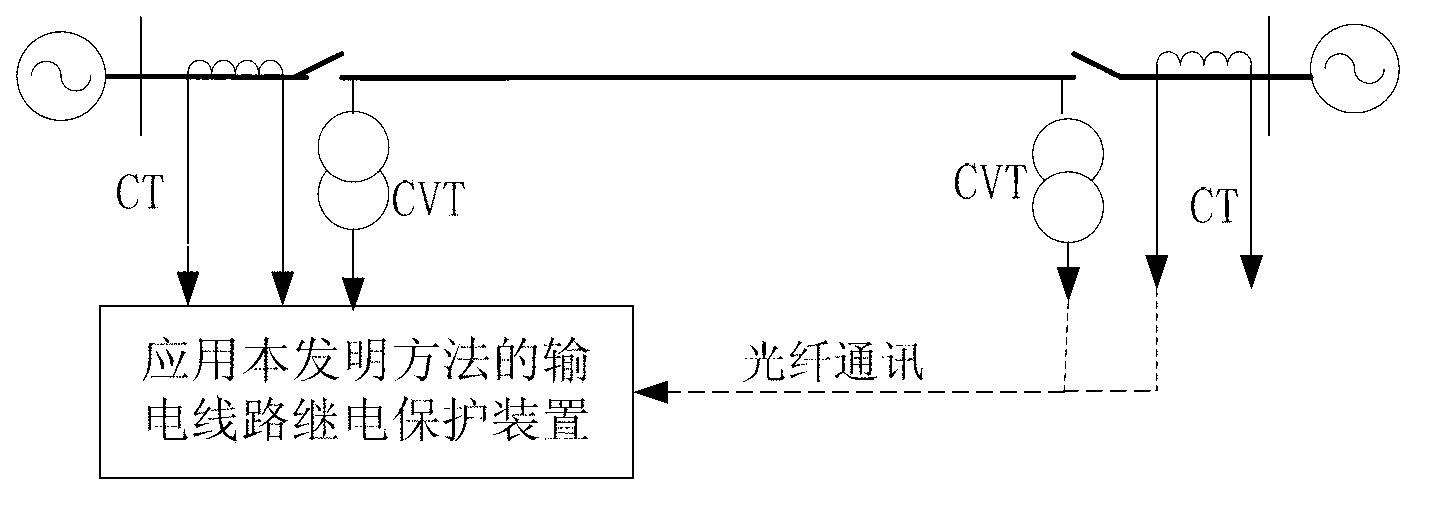
[0014] figure 1 It is a schematic diagram of the line transmission system applying the present invention. The protection device measures the A-phase current of the transmission line at the protection installation of the m substation , Phase B current , Phase C current , to measure the A-phase current of the transmission line at the protective installation of substation n , Phase B current , Phase C current .

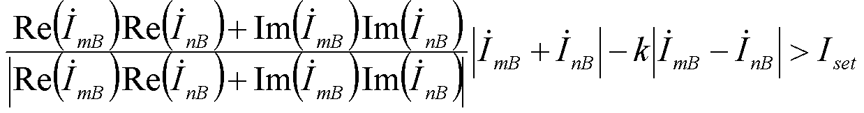
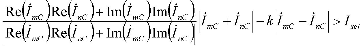
[0015] Protection device judgment Re ( I . mA ) Re ( I . nA ) + ...


PUM


Abstract

The invention discloses a directional current differential protection method of a power transmission line. The method includes computing a real part of a ratio of current of one end of the power transmission line to current of the other end of the power transmission line, dividing the real part of the ratio of the current of one end of the power transmission line to the current of the other end of the power transmission line by an absolute value of the real part of the ratio of the current of one end of the power transmission line to the current of the other end of the power transmission line to obtain a direction coefficient and utilizing the direction coefficient, differential current, braking current and a current set value to form directional current differential protection criteria of the power transmission line. Action performance is unaffected by unbalanced current, and action sensitivity is high. Whether current transformers are saturated or not, action can be carried out reliably and accurately when faults occur in a power transmission line protection area, locking can be performed reliably and accurately when faults occur outside the power transmission line protection area, and action performance is unaffected by saturation of the current transformers.

Description

technical field [0001] The invention relates to the technical field of electric power system relay protection, in particular to a method for differential protection of transmission line direction current. Background technique [0002] Because it is not affected by the power system operation mode and grid structure and has a natural phase selection function, the current differential protection has always been the main protection of various voltage levels of transmission lines. In 220kV and below voltage level transmission lines, since the distributed capacitance current along the transmission line is very small, the influence of distributed capacitance on the operation performance of current differential protection is very small. The voltage and current transmission of EHV / UHV transmission lines have obvious wave process, and the distributed capacitive current along the line is very large, and the distributed capacitive current and the transmission error of current transforme...

Claims


Application Information

Patent Timeline
IPC IPC(8): H02H7/26
Inventor 林富洪曾惠敏
Owner STATE GRID CORP OF CHINA
Why Eureka
Try Eureka